UWSGARY
|
 posted on 23/5/08 at 05:19 PM posted on 23/5/08 at 05:19 PM |

|
|
Chassis Weight
Hi all... I have constructed a computation model of the locost chassis, trying to find out the torsional stiffness of the chassis....
I have a question, what is the weight of the chassis , as after I constructed the chassis with 2mm wall thickness steel beam, the software is trying
to tell me the chassis weight
Total Mass of Model: 4.982908e-02 in Tonnes
Therefore it means 49.8kg which means very light I guess for a chassis. what kinda number I should expect???
Anyone got any figures on torsional stiffness of the real chassis as I am trying to compare the computation model to real chassis.
Thanks 
|
|
|
|
|
UWSGARY
|
| posted on 23/5/08 at 05:33 PM |
|
|
Oh yes forgot to mention it is a bear chassis that I have constructed so far in the model, which is based on the Hayes Manual book. The chassis is is
without all mounting brackets.
Once I have completed the analysis I am more then happy to share it with the forum members, but currently need some info hope that you guyss can help
|
|
|
Mark Allanson
|
| posted on 23/5/08 at 06:03 PM |
|
|
Add 5 kg's of mig wire, 13 bone brackets, seat belt mounts, nose cone tabs, radiator mounts, roll bar............
If you can keep you head, whilst all others around you are losing theirs, you are not fully aware of the situation
|
|
|
Simon
|
| posted on 23/5/08 at 06:03 PM |
|
|
When I made my chassis (but before I added floor), it could easily be picked up and iirc it weighed about 35 - 40kgs.
My chassis is 16swg which is 1.6mm.
ATB
Simon
|
|
|
Mark Allanson
|
| posted on 23/5/08 at 06:11 PM |
|
|
Having said that....
Rescued attachment Chassis weight2.jpg
If you can keep you head, whilst all others around you are losing theirs, you are not fully aware of the situation
|
|
|
speedyxjs
|
| posted on 23/5/08 at 06:11 PM |
|
|
Mine is 6 inches longer and made of 2mm rhs and i cant lift it without help 
[Edited on 23-5-08 by speedyxjs]
How long can i resist the temptation to drop a V8 in?
|
|
|
UWSGARY
|
| posted on 23/5/08 at 06:26 PM |
|
|
Thanks guys. so more or less I am on the right track in the computer model. As the software it assumes the beams very perfect joint, and welds are
perfect strong (although it is clearly isn't the case in real life).
I have done a inital test on the chassis, as I have marked out the suspension moutning points as these are the point where the load are loaded to the
chassis.
But based on 100N up and 100N down on the front suspension mounting point on chassis and constrainted the chassis at rear suspension mounting points
(therefore simulating a twisting moment) we see 1.9mm of deflections :S
I will get some results up later on after going out for some food
[Edited on 23/5/08 by UWSGARY]
|
|
|
mr henderson
|
| posted on 23/5/08 at 06:59 PM |
|
|
quote:
Originally posted by UWSGARY
I have done a inital test on the chassis, as I have marked out the suspension moutning points as these are the point where the load are loaded to the
chassis.
But based on 100N up and 100N down on the front suspension mounting point on chassis and constrainted the chassis at rear suspension mounting points
(therefore simulating a twisting moment) we see 1.9mm of deflections
I suppose 1.9 mm isn't too bad, depending on whether the load described is a small, medium or large one in real usage terms
|
|
|
britishtrident
|
| posted on 23/5/08 at 08:06 PM |
|
|
A lot will depend on the restraints used on the model.
|
|
|
UWSGARY
|
| posted on 23/5/08 at 09:01 PM |
|
|
I done that test just as a test of water, it is not the real load case by any means. Infact it will be far less then the real load case. The reason
being is (pending on driver an setup) I guess it will see above 1g lateral load for really throwing around for competition ones will see more.
I am guess the car will be around 550kg in weight, what about weight distribution??? F:51% R:49% seems reasonable as a guess??
I will get some pictures up shortly, as just came back from dinner
|
|
|
UWSGARY
|
| posted on 23/5/08 at 09:24 PM |
|
|
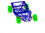
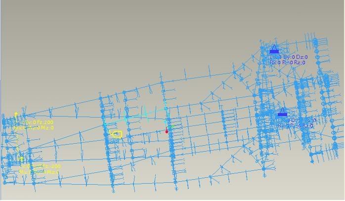
Here is some pictures from the test I have done: -
This is the chassis that being modelled, some changes were made to allow the test being done: -
1) Rear Suspension Mount point is a box section (without the bottom plate), however the software that I got not allow or I just don't know show
to mix the solid model into it (as it is done based on beams)...... Hence the rear mounts I just beams instead and found the center point as the
suspension mount point for constraints.
2) Constraints are done based on it fixed all axis X,Y and Z and not free to rotate. Note that this model x is across the car, y is along the car, z
have its usual meaning vertical of the car.
3) Load were applied at the front of the car on the top rail where the suspenion mount is according to the Haynes Maual Drawing.
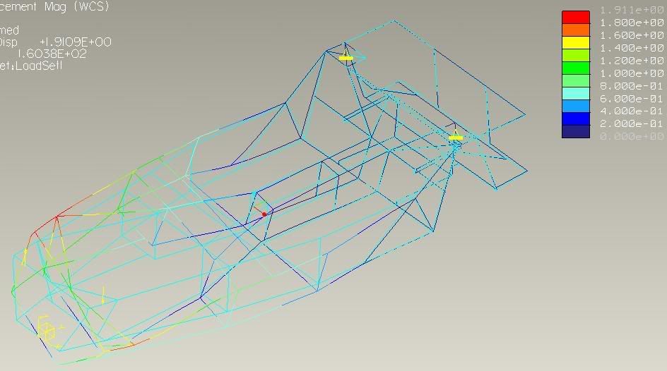
The Result: -
The Cyan coloured lines are the original location of the beams. The rainbow coloured ones shown the chassis deformed, with colour scale on right in
mm.
I am just thinking, next to run a test with more realistic load case. However anyone knows if I should take into account that the shock are not
mounted vertical (for outboard mounted ones) so there will be a magnitudes of forces???
If so anyone can have a rough measurement and share the figure the angle of the shock is mounted?
Last I probably run a 5g loading to the model as abuse load and it will never see that kind of load but just as an idea before I start modifying the
chassis to reduce flex..
If anyone holds any info or can lead us to info on the chassis stiffness (if you have measured one before) it would be great as then can compare
against the computation result against the actual result...
Your contribution would be much appreicated as this is my final year project... whatever finding I found I am more then happy to share and a way
to say thanks to all of you that contributed
[Edited on 23/5/08 by UWSGARY]
[Edited on 23/5/08 by UWSGARY]
|
|
|
D Beddows
|
| posted on 23/5/08 at 10:08 PM |
|
|
Someone has done almost exactly this before with a Luego Locost chassis, can't remember who but it was for a dissertation as well if I recall.
I've got it on my computer somewhere so if you insist on reinventing the wheel u2u me an email address I'll happily send it over.
[Edited on 23/5/08 by D Beddows]
|
|
|
andyd
|
| posted on 23/5/08 at 10:47 PM |
|
|
Reinventing the chassis in any case. 
How about doing the same thing on... oh I don't know... a mid-engined Lotus Elise sized chassis?  
Andy

|
|
|
UWSGARY
|
| posted on 23/5/08 at 11:13 PM |
|
|
Cheers guys... I am really corcerning the way I constrainted the model.... as this have significant effects on the result obtained. I am not sure if
the way I have constrainted so far is correct.. As I have done a search there seems to be FEA expert onboard here hope that they can shade some light
As I have tried another method (by allowing one of the rear corner to translate in X and Z direction and also free to rotate at X and Z the
chassis deflected 22mm!!!) Under its own front mass loaded half to left up and half to right down..
Andy what you have got in mind?? You got details? Would be interesting to see but would be after this final year project, if you want to provide some
details I am more then happy to help.
[Edited on 23/5/08 by UWSGARY]
|
|
|
andyd
|
| posted on 23/5/08 at 11:23 PM |
|
|
Well that's the problem at the moment... most of it is only in my mind! LOL.
I will at some point have my chassis design in a showable state but I won't be holding my breath quite yet.
Once I'm there I will be asking all you kind people for constructive criteque as this'll be my first attempt. It'll be at that stage
that it'd be good to know the numbers before and after changes before commiting it all to steel.
Andy
|
|
|
TheGecko
|
| posted on 24/5/08 at 01:08 AM |
|
|
OK, first the disclaimer. I am not an FEA expert . At all. Not even a little bit But I've read a LOT about FEA on here and other boards
over the last few years.
Everything I've read suggests that you're over constraining your model. The tests I've read about usually seem to take the approach
of constraining one back corner X:Y:Z, the other back corner in 2 dimensions (probably free up the transerve axis) and the front corner opposite the
applied load in vertical (Z in your model?) only. And yes, the standard Locost chassis is as floppy as a very floppy thing! To meet torsional
strength requirements in Australia there's a fair bit of extra bracing usually added. Search for "Aussie Mods" for more.
Hope this helps,
Dominic
|
|
|
UWSGARY
|
| posted on 24/5/08 at 02:01 AM |
|
|
Thanks Dominic I shall give the constraint you suggested a try later on. I am using ProE software as it can be a bit of a pain. Just figured out
how to do shear panels in the software (as no lecturer knew in Uni..) But it is taking forwever to run. As soon as that finish I shall try it
Will post up some more results up tomorrow after work...
Afterall student don't get a easy life do we
|
|
|
Simon
|
| posted on 25/5/08 at 07:07 PM |
|
|
Imho, unless you are doing something drastic to the design of the chassis, I'd have thought you'd be better of not playing around with the
pc, and getting on with welding up a chassis
ATB
Simon
|
|
|
UWSGARY
|
| posted on 30/5/08 at 07:58 PM |
|
|
I now got some result from computation model and also used a wood model for torsional testing...
The lecturer loved the presentation and thanks to all the people that have helped Now just need to write up the 40 page B*gger... LOL I will put
the results up later on as I am trying to upload them to host.
However the computation results shown big improvment by attaching the body panels as they were used as shear panel in the model, that stopped
considerable amount of flexing.. Infact it achieved very similar results compared to using beams and panels. As steel beams are more heavier compare
to the aluminium panels.... + the fact the car will need panelled anyway.so that keep inline with the Colin Chapman's "multitasking
component" theme LOL
[Edited on 30/5/08 by UWSGARY]
|
|
|