
This morning I saw a GTM on the way to work witch got me thinking about Composite chassis. Does any body have a link to the manufacture of a Composite chassis GTM or other. There was thread in the three wheal section a while back but I cant find that now.
Westfield made a composite chassis car a few years ago. FW400 I think it was called. 400kg but OMG expensive.
Id rather like the idea of a monocoque carbon fibre chassis for my kit..... if i had the money!
quote:
Originally posted by MakeEverything
Id rather like the idea of a monocoque carbon fibre chassis for my kit..... if i had the money!
Send your drawings to these guy´s
http://www.atrgroup.it/
They have some experience.
Think this is the thread you're talking about
http://www.locostbuilders.co.uk/viewthread.php?tid=94561
The link to the trimagnum grp over foam approach is here
http://www.rqriley.com/frp-foam.htm
Note there is some chassis under there, more of a big subframe really.
smart51's cabin scooter uses this method of construction, but also has a chassis. Lots of good information in his posts and photos.
[Edited on 14/10/09 by iank]
quote:
Originally posted by iank
Think this is the thread you're talking about
http://www.locostbuilders.co.uk/viewthread.php?tid=94561
The link to the trimagnum grp over foam approach is here
http://www.rqriley.com/frp-foam.htm
Note there is some chassis under there, more of a big subframe really.
smart51's cabin scooter uses this method of construction, but also has a chassis. Lots of good information in his posts and photos.
[Edited on 14/10/09 by iank]
quote:
Originally posted by ceebmoj
there was anothere 1 + 1 three wheeler that was all grp over foam with bonded in kevlar bulkheads
[Edited on 14/10/09 by ceebmoj]
quote:
Originally posted by clairetoo
Do you mean the TREV ? Linkydink
I've been reading about trev and have made some enquiries as to the cost for UK supply of the honeycomb grp material - no answer as yet.
What I have found though is this
Not sure if you'd get the strength, but if you gave it adequate skinning with carbon, kevlar or woven roving then a decent strength might be
achievable.
I had also been considering how to vaccuum bag the a monocoque using resin infusion - not only neater but I feel it would be stronger as well because
you'd have less risk of getting any air pockets trapped in there.
nasty bob from the mid engen section
http://www.locostbuilders.co.uk/viewthread.php?tid=73075
has used a skined hunny come sections to pannel in parts of his chasy maby the product he used is apropreate
also have you got any picture of how hard points are mounted to trev?
on old formula vauxall lotuses a hole is drilled and a aluum top hat inserted from both sides so tha you cant crush the center section.
That's about it - ali bobbins and also in some placs a large ali spreader panel, as well as angle in the corners etc.
No details on Trev, but have a read of 'How to Build Motorcycle Engined Race Cars' and it hs some explanation, as well as Allan Staniforths
'Race and Rally Car Source Book'. The first book is OK - not much explanation of actually building a cr but a decent bit of starter info
and plenty of ideas on how to do various things - it has a chapter on making a monocoque using honeycomb ali panels.
I have a distant plan to do something very similar but using the grp honeycomb/kevlar laminate along the same lines as Trev.
as in this book?
http://www.amazon.co.uk/s/ref=nb_ss?url=search-alias%3Daps&field-keywords=How+to+Build+Motorcycle+Engined+Race+Car&x=0&y=0
That's the one.
It's OK, but there again I picked up my copy for Ł6 (brand new) from an autojumble.
I also managed to get hold of an original, unopened copy of High Speed, Low Cost for Ł25 from the same guy
My car is made out of honeycombe. A few bad pics in my folder. If I ever did it again I would make jigs and have inserts placed beteen the sheets and
use laser cutting. I would also use solid bulkheads - or maybe just steel tube???
On the ther hand the locost shape might lend itself to 2 substantial side planks of honeycombe. I would go for 40mm 1/8" cell carbon/kevlar - no
need to paint it either!!
I got my sheets from Aim Composites - they were good to deal with and were happy to make sheets up in Kevlar/carbon. They would have put in inserts.
None of this was what you would call Lo Cost
Right, just got my email quotation from Ayres (the company that does the stuff Trev is made from).
372 euros per sheet, which sounds quite a lot but by my figuring I reckon a single seater would be made from 3 sheets, so a monocoque single seater
chassis for Ł1k (plus the cost of laminating in carbon/kevlar).
Probably need to price it up using cheaper materials because it'd be a bloody shame to make something that epxensive to fin a fundemental flaw in
the design that needs changing (ie, a hole new chassi building).
Can you laminate ali panels with compsite materials successfully/strongly?
what about the Nidaplast you posted about before it also come in a other
thickness as well
[Edited on 15/10/09 by ceebmoj]
I'm just not sure how string the nidaplast would be compared to ali honeycomb.
I might try an experiment by buying some and a small quantity of carbon, kevlar, carbon/kevlar and woven roving and see what works.
I think that with care and preferably some heat you could get a decent bond between aluminium and Carbon/kevlar even in a diy situation. Just pay attention to joint design.
www.darrian.co.uk
mosler are made from composite panels bonded together .
using this stuff .
www.teklam.com
my chassis has bonded in kevlar/carbon panels .
But can you bond carbon/kevlar to ali panels to add strength. Not so much strength in the bending of the panel, but a whole ali monocoque laminated to unify the structure properly (if that makes sense?)
in my opinion , bonding kevlar/carbon/grp to ali isnt really applicable in DIY situations since the need for temperature control and the surface
preparation needed .
time has moved on , there maybe products/applications that would work , but, theres no reason to have carbon/kevlar bonded to ali since the composite
is much better at doing it .
if you look at the teklam site , you can indeed get get honeycomb section with ali one side , carbon the other .
You just want t be able to do this:
Have you been following Denis Palatov's progress on the composite chassis for his DP1?
The pages on the composite chassis are in the "past" logs on www.dpcars.net
http://www.dpcars.net/dp1test/dj.htm
http://www.dpcars.net/dp1v8/da.htm
http://www.dpcars.net/dp1v8/db.htm
He's built his second prototype chassis using honeycomb and a thermoset adhesive.
Doesn't look particularly low cost, OK, doesn't look at all low cost but does look exceptionally well thought out.
t
The Teklam products are very similar to those offered by Ayres as used on Trev.
The advantage I see of using the composite panels over ali panels is that once the monocoque is formed, an overall skin of woven roving, carbon or
kevlar (budget allowing...) can be added to put some extra strength to the whole thing.
Obviously it will take a serious amount of planning to get it right and I though of starting with a steel speceframe to get the suspension right
first, then construct a monocwue to mount everything to.
Of course it's all an exercise in 'because I can/might be able to'....
quote:
Originally posted by nasty-bob
Hi
Honeycomb panel was supplied by Technical Resin Bonders and cost about Ł250 for a 8 x 4 sheet 1/2 inch core sheet.
The carbon/kevlar was from East Coast Fibre Glass Supplies
Cheers
Rob
The Ayres product used in TREV is a honeycomb panel with GRP faces rather than aluminium. They use epoxy resin and a woven mat. A friend who runs a
CNC routing business has a few samples.
I think a good approach with this material would be to use it partly as a structural material and partly as a core in your planning.
It would be possible to get a laminate to make a good bond with some surface prep. The choice of reinforcement I would choose would be carbon fibre.
Kevlar is an excellent fibre but it is an absolute mongrel to cut and almost impossible to sand. It fuzzes up something chronic and will drive you
nuts.
The epoxy GRP honeycomb product is substantially cheaper than the aluminium faced types and I think it would be an excellent choice particularly if
you had it cut on a large scale CNC router.
Laser cutting isn't very suitable for aluminium, youre better off cutting it with a rotating tool or a water jet. The GRP stuff could go on a
laser but the cost per hour compared to CNC routing is much higher. Any decent kitchen manufacturer would have a CNC router up to the job.
As to design, never feed a load into an unsupported face, only into a supported edge or corner. A good method would probably be to use the HC sheet
to make the length of the monocoque and steel to make bulkheads and suspension/engine/steering pickups and structures. The spaceframe components
could bolt to lugs or bobbins laminated into the structure.
The biggest downside to this is if you crash it and bust it, you'll have to replace the monocoque part completely.
youve just described how the mosler chassis is made .
it uses 1 inch teklam sheet (ally honeycomb with nomex/grp mix) , the inside is laminated with carbon and kevlar , the roof structure is carbon and
bonded to the honeycomb chassis .
the rear engine/ suspenion subframe are bolted through bobbins into the chassis as is the front .
the floor section is purposely left long to support the rear subframe as it rests on it , it bolts upwards at the front .
they use large bobbins to bolt everything in .
i cant believe how easy it all looks , a guy with a router and some straight edges could easily make it .
quote:
Originally posted by Volvorsport
i cant believe how easy it all looks , a guy with a router and some straight edges could easily make it .
quote:
Originally posted by StevieB
I guess an easy way to get a template and refine the design is to build a mock up out of ply wood...
Plywood would be the only "engineered" wood product I can think of and compared to using honeycomb as a core, it would be extremely heavy
for the thickness. Speaking of which, it's the thickness of the core that increases the strength of the panel.
Frank Costin made a super little car out of plywood, don't remember the model. He was also known to have used plywood for other projects aimed
at improving car aerodynamics.
So plywood is definately doable but not as a core so much unless your design aims can be achieved with relatively thin panels.
TREV used 20mm panels that were routed part way through, then bent at the cut, preserving the skin on the outside of the curve/radius. Using simple
jigs, the bent panels are held in place while a lamination of reinforcement was laid over the assembly. when it cures, the shape holds nice and
simple! You could do a whole centre section of a seven like this.
Properly designed and cut, you might only need two or three pieces to make the tunnel/passenger/sides part of the chassis. It would weigh a heap less
than steel tube as well.
A monocoque se7en using this technique should be fairly simple (famous last words...), with my thoughts being to build the cockpit and engine bay as
one with subframes front and rear to carry suspension and diff, though I ould extend the floor so that it's fully flat bottomed (and put an F1
style plank on the bottom as a sacrificial layer).
With a bit of planning, you could make it to take boywork from a normal se7en type car (whoever currently supplies locost bodywork...).
I suppose it depends on how much lighter the end result would be compared to a steel spaceframe.
I would only use plywood as a proof of concept and final template, not for the final shssis as it's too heavy.
At least with carbon skins you would not have to have a love affair with rivets.........

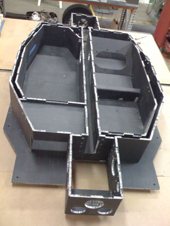
A view from above - front pinned on
Very impressive ^^^^^^^^^^^^^^^
What is this a chassis for? The dedication to do all those rivets is admirable. Not forgetting of course, that every hole needs to be deburred prior
to seating the rivet. Massive time/effort.
Dedication....there are days when I wished the shed would burn down. Each hole is drill, debur between sheets, drill to size and debur again -
countersink for some holes - apply glue - then try and work out why all the holes have moved.....
If I started again I am not sure I would use aluminium. My tub is not that light - circa 100kg. It is probably fairly stiff and will be more so when I
add front stays to a roll hoop.
Back to the topic - I think that a carbon honeycombe tub for a 7 style car would be a lot simpler. I think that it has already been done. There is
honcombe and honeycombe so beware. It is also used for things like exhibition stands etc and designed to look pretty. Specifying 1/8" cells is a
good idea.
It is fairly easy to bond in inserts but even easier to have then bonded in when the panel is made. Yoou would need a jig - a group buy perhaps..
I have not made a great job of load paths at the front of my car and have all sorts of internal reinforcement adding to the weight. The suggestion of
tubes from the bulkhead forward would certainly simplify things - that was my plan A and I wish I had stuck with it. The rear ought to be fairly
simple though provided that there was a substantial bulkhead behind the seats.
I would make the scuttle structural - a good few layers of CF.
I would make a cardboard model 1/4 - cheeper and more acceptable on the kitchen table. Then a wooden full size model.
I would endorse the suggestion of a cnc router - I did mine by hand...awful!
Given that a measuring error would not be reversable I would gather together all of the bolt on bits before bonding anything.
quote:
Originally posted by Benonymous The choice of reinforcement I would choose would be carbon fibre. Kevlar is an excellent fibre but it is an absolute mongrel to cut and almost impossible to sand. It fuzzes up something chronic and will drive you nuts.
Kevlar would definitely be the best choice for puncture resistance and if you just cut a section that had no need to be trimmed and put it in the layup, it wouldn't provide you with too much grief. CF would not give you the same properties as Kevlar but I don't see it as being a major problem if you had a 20mm panel and CF reinforcement it would be more puncture resistant than say an aluminium floor.
hi,
this is my attempt at some cad of a tub all 20mm core to be covered in resen and fabric what do people think?
Its a 60s inspired single seater. the curved side panels will be lade up seporatly then bonded on to the tub

compersit tub
[Edited on 22/10/09 by ceebmoj]
Is that rear engine - feet through the window of the middle bulkhead?
I would try to design out the small fillet on the inside bottom.
Where are your suspension loads going?
One thing I think I got right is a fully stressed seat base - a fully stressed back would help.
Are you aiming for a semi stressed engine but a fully stressed gearbox? If so you need to think how you will attach your engine plate/adaptor. You can
have inserts bonded in when the panel is made.
A 60's style car gives you a nice choice of transaxles if you go for engine in the back - Hewland Mk 9 boxes are very reasonable.
quote:
Originally posted by TheshedIs that rear engine - feet through the window of the middle bulkhead?
quote:
Originally posted by Theshed
I would try to design out the small fillet on the inside bottom.
quote:
Originally posted by Theshed
Where are your suspension loads going?

quote:
Originally posted by Theshed
One thing I think I got right is a fully stressed seat base - a fully stressed back would help.
quote:
Originally posted by Theshed
Are you aiming for a semi stressed engine but a fully stressed gearbox? If so you need to think how you will attach your engine plate/adaptor. You can have inserts bonded in when the panel is made.
A 60's style car gives you a nice choice of transaxles if you go for engine in the back - Hewland Mk 9 boxes are very reasonable.
That looks good to me - would you do the outer skin with honeycomb as well?
I need to get a copy of CAD in order to plan out my own design! Looks much neater than my hand sketches
I was thinking of just laying up the side panels out of two layers of cloth and resen with a gell cote and then bonding them on to the tub.
my uprights are out being machined at the moment so after that I will make up a MDF tub and do a build up with that
quote:
Originally posted by ceebmoj
also does the GTM use CF / kevlar in its tub?
quote:
Originally posted by Theshed
Are you aiming for a semi stressed engine but a fully stressed gearbox?
quote:
Originally posted by Uryen
quote:
Originally posted by Theshed
Are you aiming for a semi stressed engine but a fully stressed gearbox?
Could you explain what this means?
Does it mean the engine and box are part of the frame structure like in some extruded aluminum bike frames?

Yup that's what I meant ^^ What I meant by "semi stressed" was that the engine would be solid mounted but braced by some part of your
composite structure.
I would think about a nice big plate across the back of the structure to tie everything together.
Excellent plan to start with the uprights and work inwards.
If you look on GT40s.com in the build logs you will see somebody building a carbon tub using mdf to make moulds etc
John
composites or 2 layers of structural material (aluminium, fibreglass carbon fibre whatever) sandwiching a spacing material are far stronger and
lighter than the moulded fibreglass type construction.
using woven glass and epoxy resin sandwiching foam will be far cheaper than the honeycombe materials although forethought and planning is paramount as
reinforcing needs to be built in rather than just bobbins as the foam material will crush more readily.
Its also easy to produce curved components.
The processes are very well documented in the kit aircraft market, i believe the techniques originally pioneerd by Burt Rutan and used in many of the
worlds most popular and numerous homebuilt aircraft
aitch
p.s. new here and thinking aloud please be gentle with me
[Edited on 2/12/09 by aitch]
[Edited on 2/12/09 by aitch]
Ive re-read this whole thread and the links
the Nidaplast cores are very interesting, i would be more concerned about heat resistance than strength, however these cores would make possible a
locost composite chassis that is TRULEY LOW COST more expensive aluminium honeycombe could be used in the areas that need the heat resistance, id opt
for woven glass and epoxy over most of the structure to keep costs reasonable, although carbon and or kevlar could again be used in some areas either
for strength, puncture resistance or asthetics
http://www.cfsnet.co.uk/acatalog/Nidaplas_Polypropelene_Core.html they also provide links to use and application of the core material which would be
invaluble in planning the build
The Palatov Chassis uses composites to create a series of box sections, a technique which followed will create incredibly strong and rigid
structures
aitch
im going to use some of this time to come up with a concept
[Edited on 3/12/09 by aitch]
as it says good pic of the palatov chassis showing the box sctions created
aitch

Rescued attachment dp1017.jpg

also been talking with the technical Guy at CFS (Alex) and on the choice of resins and cloth his opinion is that polyester resins and chopped matt
would be more than adequate, if so the costs would fall drmatically compared to woven cloth and epoxy resins.. defonately some structural tests
needed..
Im only at the thinking about it stage although anyone ready to get started i am sure Alex at CFS will be more than helpfull
aitch
[Edited on 3/12/09 by aitch]

Rescued attachment Kit Car.JPG
I’m a stress analyst working in the aerospace field with nearly 25 years of experience – maybe half of that (or better) is working with composites;
so, when I see a topic like this I feel a bit compelled to chime in. You can believe what I will tell you or not – I’m not trying to sound arrogant,
and there are people who know more about composites than me, but as a percentage of population, not so many.
quote:
Originally posted by smart51
I love it when people step into this bear trap. It's even better than CEC vs BEC.
Basically, Ali is too brittle for the vibrations seen by a space frame chassis and will snap before too long. It may be all right for a car you're going to use once (say you're entering the lemans 24hr) but not for regular use.
quote:
Originally posted by Benonymous
I think a good approach with this material would be to use it partly as a structural material and partly as a core in your planning.
quote:
Originally posted by Benonymous
It would be possible to get a laminate to make a good bond with some surface prep. The choice of reinforcement I would choose would be carbon fibre. Kevlar is an excellent fibre but it is an absolute mongrel to cut and almost impossible to sand. It fuzzes up something chronic and will drive you nuts.
quote:
Originally posted by Benonymous
The epoxy GRP honeycomb product is substantially cheaper than the aluminum faced types and I think it would be an excellent choice particularly if you had it cut on a large scale CNC router.
quote:
Originally posted by Benonymous
Laser cutting isn't very suitable for aluminum; you’re better off cutting it with a rotating tool or a water jet. The GRP stuff could go on a laser but the cost per hour compared to CNC routing is much higher. Any decent kitchen manufacturer would have a CNC router up to the job.
As to design, never feed a load into an unsupported face, only into a supported edge or corner. A good method would probably be to use the HC sheet to make the length of the monocoque and steel to make bulkheads and suspension/engine/steering pickups and structures. The spaceframe components could bolt to lugs or bobbins laminated into the structure.
The biggest downside to this is if you crash it and bust it, you'll have to replace the monocoque part completely.
quote:
Originally posted by aitch
as it says good pic of the palatov chassis showing the box sctions created
aitch
kennyrayandersen
obviously WAY more experienced and knowledgeable than i, and i always appreciate imput especially when its negative as the posibble outcomes are
horrific..
ive no idea what kind of stress analysis the petrov people have done, somehow the box sections in the chassis tub just "LOOK" right when
compared to wing spars and cockpit tubs of the homebuilt aircraft, however possibly light on structure and load paths around the suspension mounting
areas ????
aitch
Some great points there Kenny - hopefully I am one of the few who does know enough to add to this - you have raised some very valid arguments. I typed
this and walked away, and you had covered most of the points I was going to touch on, so I won't repeat too much....
aitch - If you are being advised to use CSM and polyester, then the design of your chassis must be pretty pants! What is the point of going for a
composite chassis, if you don't fully utilise the benefits of composites. If you use CSM, you will add a significant chunk of weight and reduce
the mechanical performance considerably (CSM is only 1/3 the stiffness of a unidirectional material).
you seem to have designed/built that as if you were building out of an isotropic material (which CSM effectively is in X and Y directions), but
composites come into there own when you consider them as the anisotropic materials they are. Consider you load paths, and consider youravaiobale
materials, mabnufacturing techniques, inspection methods etc.
Are you doing this as a learning exercise, or to get the lightest, stiffest chassis you can? That will make a big difference to how you can progress
from here....
quote:
Originally posted by twybrow
Some great points there Kenny - hopefully I am one of the few who does know enough to add to this - you have raised some very valid arguments. I typed this and walked away, and you had covered most of the points I was going to touch on, so I won't repeat too much....
aitch - If you are being advised to use CSM and polyester, then the design of your chassis must be pretty pants! What is the point of going for a composite chassis, if you don't fully utilise the benefits of composites. If you use CSM, you will add a significant chunk of weight and reduce the mechanical performance considerably (CSM is only 1/3 the stiffness of a unidirectional material).
you seem to have designed/built that as if you were building out of an isotropic material (which CSM effectively is in X and Y directions), but composites come into there own when you consider them as the anisotropic materials they are. Consider you load paths, and consider youravaiobale materials, mabnufacturing techniques, inspection methods etc.
Are you doing this as a learning exercise, or to get the lightest, stiffest chassis you can? That will make a big difference to how you can progress from here....
Thanks for the clarification.
Don't be too hasty to give up, but just have a think as to what you are aiming to achieve. You could gain plenty of knowledge by going to your
local library, and start reading! There are sooo many books out there on composite design.
Can you use a CAD package? FEA? Have you ever designed/manufactured anything in composite before?
quote:
Originally posted by twybrow
Thanks for the clarification.
Don't be too hasty to give up, but just have a think as to what you are aiming to achieve. You could gain plenty of knowledge by going to your local library, and start reading! There are sooo many books out there on composite design.
Can you use a CAD package? FEA? Have you ever designed/manufactured anything in composite before?
purely a proof of concept
http://www.tech.plym.ac.uk/sme/acmc/download/chass.pdf
aitch
p.s. looking forward to months of reading and learning
^ That was my dissertation supervisor back in the day! He knows his onions!
Some more reading for you:
Here
Here
You'll like this one
Here
[Edited on 3/12/09 by twybrow]
quote:
Originally posted by twybrow
^ That was my dissertation supervisor back in the day! He knows his onions!
Some more reading for you:
Here
Here
You'll like this one
Here
[Edited on 3/12/09 by twybrow]
I wrote that quite late at night, so maybe I was a bit grumpy; however, the points were pretty much valid. The problem with the Palatov chassis is
primarily that the vertical panels he has in the back don’t line up with anything else; so, when the load gets to the bulkhead it’s reacted as
bending, which is the least efficient possible way to do it. The reason one adds honeycomb core to two thin facesheets is to make the panel more
stable [it’s still got to carry the load]. The catch there is that when the load gets to the edges of the panel, you have only these 2 thin
facesheets to react the load. In aluminum, the bearing allowable is around 120-130 KSI ultimate, so you can make the core tapered at the edges and
form the aluminum facesheets and get away with having thin edge members.
Conversely, the composites are much worse in bearing. Without a lot of sophisticated software, you could use a value of 60 ksi (for graphite epoxy
which has been cured in an autoclave) which is around half of aluminum. Therefore, with the composite facesheets you need to [typically] add extra
plies around the boarders of the panel for bearing strength – the core still typically has to be machined, or purchased as a pre-machined detail to be
made into a composite assembly. I took a quick look through some of the links that twybrow posted and you’ll not that some of those techniques will
only work with aluminum core and facesheets, since they require the ability to crush the core or yield the facesheets in bending – nether of these are
permissible with graphite or fiberglass as it will catastrophically fail the panel. And actually it’s not such a great idea in aluminum either as the
crushed core just isn’t the same (pre-failed?).
Generally, you note that most composite race cars and such use the material to make a monocoque-type tub of sorts where the panels can be loaded
primarily in shear. The trick, then, is to get the loads which are introduced at singular points in to broader shear loads in the composite panels.
This is done with the fittings and such that I mentioned in my earlier post. It’s not that it can’t be done of course, but you will likely need your
own machine shop or be prepared to ante up to have the work done ‘out of house’.
Let’s say a decently designed and fabricated steel locost chassis weighs what? 85-100 Lb? Let’s say for the sake of argument that you’re a
über-genius such as myself (tongue-in-cheek). Maybe I could get the weight down to 65-75 Lb using finite element analysis and what I know about
composites (which as any actual genius knows – no one can know that much about anything).
What did I actually ‘pay’ to make this happen.
1. Time, initial -- extra design and analysis time
2. Money -- from something nearly any bloke with a paper route could buy to something that has to be funded by NASA – this is just with regard to
materials
3. Time , manufacturing – briefly, labor INTENSIVE. What was a couple of weekends has now gone on to a couple of months… or years
4. Facilities – where you going to get that autoclave?, or will you ‘settle’ for the lower allowables from a room temperature system? McLaren bakes,
enough said.
In summary, to save 25 pounds, you sold your soul and you left testicle to the devil (who was in the details). A body is a different story
altogether, but we are talking chassis here. If a steel chassis is good enough for the Ł39,275 pound Caterham Superlight 500 (and might I add
super-fast), it’s good enough for yours!
[Edited on 4/12/09 by kennyrayandersen]
Thanks for your input Kenny. There's no doubt that the good old steel space frame is pretty hard to beat. The weight comparisons you made are
really quite startling if they are accurate. So its a few hundred quids worth of steel up against thousands of quids worth of composites.
Still the garage culture will carry on and the amateurs will eventually figure out what value they can get from these sorts of materials. The main
thing that's lacking at the present time is readily available information on using composites.
By contrast, there's no end of info about steel and welding. We will have to wait until carbon fibre is used to make commonly used items and is
no longer a black art.
Personally, I'd never consider making a chassis out of composite unless I'd prototyped it in some way and possibly done some FEA in
SolidWorks or something similar.
Without people experimenting with the stuff, the average bloke has no hope of using carbon. I'd happily build something out of it if I thought I
could make it safe. I already have a vacuum bagging rig and soon I hope to have a medium sized CNC router to make moulds and plugs with.
quote:
Originally posted by Benonymous
Thanks for your input Kenny. There's no doubt that the good old steel space frame is pretty hard to beat. The weight comparisons you made are really quite startling if they are accurate. So its a few hundred quids worth of steel up against thousands of quids worth of composites.
Still the garage culture will carry on and the amateurs will eventually figure out what value they can get from these sorts of materials. The main thing that's lacking at the present time is readily available information on using composites.
By contrast, there's no end of info about steel and welding. We will have to wait until carbon fibre is used to make commonly used items and is no longer a black art.
Personally, I'd never consider making a chassis out of composite unless I'd prototyped it in some way and possibly done some FEA in SolidWorks or something similar.
Without people experimenting with the stuff, the average bloke has no hope of using carbon. I'd happily build something out of it if I thought I could make it safe. I already have a vacuum bagging rig and soon I hope to have a medium sized CNC router to make moulds and plugs with.
Ok what sort of cost am i looking at to get a CAD package with FEA and suggestions or recomendations as to which one i should go for
aitch
ok had a look around at some cad packages for medelling and FEA tools to go with them,,
unfortunately way out of my price range and for a one off prototypes of chassis parts and testing to destruction would be more cost effective (along
with advise from someone in the knw to get basic design concept)
You can pick up dodgy copies of most on the internet.
I used ProEngineer/ProMechanica, but it isn't the best package out there in terms of interfacing witother packages.
CATIA seems to be the most widely used CAD package, and
NASTRAN seems to be used extensively for FEA in the composites world.
FEA......another hot potato
Without a good deal of conventional experience (read years of calculators and number crunching) FEA is at best just a rough guide. If, of course, you
can even get to work in the first place...most are very un-user friendly.
It's a bit like saying being able to use MS word makes you an author......just because you can churn out some nice coloured plots doesn't
make you a stress analyst.
Just a little rant in general, certainly not having a go at anyone in particular.
www.darrian.co.uk
what do you make of these then kenny ?
FEA packages
First, not many packages that are good at designing and solid modeling are good at FE modeling and vice versa. All of the people around me that
design use CATIA V5, which will cost you both your stones and one kidney. The package that I use for FE work is NASTRAN, which is obscenely expensive
and which also requires a preprocessor – I use PATRAN (both are MSC products) as the preprocessor (you can also use FEMAP, which is a ‘bit’ cheaper,
that some guys seem to like (my German colleague seore by it)). Each of these tools are extra ordinarily powerful, but much like a gun in the hands
of a child can do a lot of damage without proper experience and training. THere are other good packages like COSMOS etc. but the good ones, have
good support and are feature laden, so they are quite expensive, especially by DIY at home standards.
There are cheap packages, which are mostly crap, and as noted none of them are particularly easy to use. I’ve been using NASTRAN output for going on
25 years in one form or another and have been using PATRAN for maybe 15 years. The cheapest way to get to use and learn one of these packages is by
becoming a student (as stated earlier).
I wish I could tell you there is a magic button to push, or that there was some shortcut to knowledge, wealth and the attraction of stunning hotties,
but that would make me and instant liar. Even if I had a fiver for every time I saw a dysfunctional, poorly constrained and loaded and utterly
worthless [and therefore dangerous] FE model, you could just call me the Count of Monty Christo! Keep in mind these worthless models are from people
with 4-year (or more) engineering degrees and some experience – it really is that hard to do well (regardless of the advert on the FE package
website!). I really don’t think you are 1) listening, and 2) being realistic about what you are going to be able to do. If you could only channel
that determination into something that will further your understanding of the underlying principles, you’d be virtually unstoppable. I’m not trying
to dis you, make you mad or discourage you in any way. I am, given my background, trying to save you some scratch and give you some valuable [and
free] advice – this is from someone that, though not knowing much, knows a great deal more about this than most.
If you really can’t be dissuaded from diving into the pool head first, then you should consider finding a proven design and then copying it. This
might require a bit of destructive testing, but even that would be cheap compared to the path you are contemplating.
Does anyone think I’m being overly harsh here?
Darrian
It looks fine from the outside (though maybe a bit dated?). I was hoping to take a look at the chassis, but couldn’t find any pictures. In the
description, it said it used a monocoque tub, which I said in one of the earlier posts was generally the only way to go. Also, I read that March was
involved, and they have made a ton of race cars, so it probably fine structurally. Note though that my other points are all contained in this car.
It’s mostly used for racing (as opposed to the road), it’s expensive – well sorted ones were being offered at 30-40KŁ which is quite apart from the
lo-cost concept. Even a roller was 20KŁ! This just backs up what I was saying:
1) Done by people who know what they are doing
2) Expensive
3) Difficult to produce
4) Used mostly for racing where weight-savings are critical and worth the additional cost (the small difference in weight doesn’t mean so much for a
standard road car. Additionally, the robustness (due to increased weight) is actually a desirable thing for a road-going vehicle (early Lots 7’s for
instance were very light-weight but broke easily and wore out quickly – neither of which would be a plus on a street car).
[Edited on 4/12/09 by kennyrayandersen]
[Edited on 4/12/09 by kennyrayandersen]
kennyrayandersen, too harsh? no, just realistic. Not that I know 1% of what you do re designing a composite chassis, but I have worked with FEA and
CFD packages so I know just how easy it is to get very pretty pictures which show what you want to see, instead of what's going to happen!
I've also made a few carbon bike frames just for fun and to learn about the process, but they're all sitting in the loft because I
wouldn't risk using them too much for the very reasons you've mentioned. If I had an autocleave, knowledge, time to make 10's of
prototypes, a test lab etc I may be able to make something I would trust but not something I did in the garage.
Carbon is a great material, and I love making things in it, but I limit it to non critical parts, like dash boards (did that about 8 years ago) and
mountain bike mud guards. On a kit car there are loads of parts that you can do in carbon which won't kill you (or someone else) if they fail.
quote:
Originally posted by kennyrayandersen
quote:
Originally posted by smart51
Basically, Ali is too brittle for the vibrations seen by a space frame chassis and will snap before too long. It may be all right for a car you're going to use once (say you're entering the lemans 24hr) but not for regular use.
This of course is utter nonsense since composites are used for all kinds of airplanes, sporting equipment, and military applications where there is a lot of abuse and vibration. In fact, one of the primary incentives for using composites is its excellent fatigue properties. It’s a matter of design and keeping the strains below the level that any delaminations due to assorted impacts whether they be VID (visible impact damage) or BVID (barely visible impact damage) will propagate when loaded ‘normally’. Brittleness has nothing to do with anything unless you are talking about a crash where the material is expected to fail catastrophically, and where graphite will shatter quite spectacularly.
quote:
Originally posted by scootz
quote:
Originally posted by kennyrayandersen
quote:
Originally posted by smart51
Basically, Ali is too brittle for the vibrations seen by a space frame chassis and will snap before too long. It may be all right for a car you're going to use once (say you're entering the lemans 24hr) but not for regular use.
This of course is utter nonsense since composites are used for all kinds of airplanes, sporting equipment, and military applications where there is a lot of abuse and vibration. In fact, one of the primary incentives for using composites is its excellent fatigue properties. It’s a matter of design and keeping the strains below the level that any delaminations due to assorted impacts whether they be VID (visible impact damage) or BVID (barely visible impact damage) will propagate when loaded ‘normally’. Brittleness has nothing to do with anything unless you are talking about a crash where the material is expected to fail catastrophically, and where graphite will shatter quite spectacularly.
Am I missing something? Smart51 is talking about aluminium (ali) being too brittle for a spaceframe chassis and your reply stating it's 'nonsense' relates solely to composites...
One of the links in a previous post went to a .pdf file with among other things in it the chassis of the Lotus Elite. Now while I'm not going to
pretend that it was built in a felt-roofed shed in the back yard of a semi in Finchley I'd venture to suggest that it was designed with a fairly
basic set of tools where load and stress was concerned. One stand out characteristic was that the suspension mountings used to fracture, not good...
However let's say for the sake of example that I decided to build a Lotus Elise chassis from Carbon fibre and epoxy resin, using the appropriate
layup thicknesses etc. Surely this would produce a superior wet layup than glass and polyester? If this is so, then I would have a stiffer, stronger
chassis than an Elite? So maybe I wouldn't have to limit my carbon fabrications to cosmetic parts?
I respect your knowledge and understanding kenny but ultimately, experimenters will do things that engineers would never dream of and maybe even put
themselves at risk in the process. I feel that this is the way of advancement. Without these risk takers there would be no kit cars or kit planes,
ultralights or even the superb Britten V1000, made by a complete amateur in the field of engine and motorcycle chassis design. Sure, John Britten
could have crashed and died on the first corner but thanks to a bit of judicious over engineering, the concept survived and went on to be one of the
most heroic efforts in motorcycle racing of all time. Any engineer would have told him he was loopy and to give it all up and grow Petunias!

What a dull world it would be if he had eh?
I love this thread. It is fantastic when the internet brings together really useful knowledge and debate and avoids unnecessary unpleasantness just
because the contribtutors disagree.
Please keep posting Kenny experience like yours is priceless. I doubt that you will put off us loonies that depart from the steel spaceframe (that is
clearly the obvious amateur choice) so any tips you can give to save us from our own insane choices.
I have made all of my own inserts for my (aluminium) honeycomb chassis. All pure guesswork. I would love to see how it is done in the aircraft
industry. Any photos anyone?
quote:
Originally posted by Benonymous
One of the links in a previous post went to a .pdf file with among other things in it the chassis of the Lotus Elite. Now while I'm not going to pretend that it was built in a felt-roofed shed in the back yard of a semi in Finchley I'd venture to suggest that it was designed with a fairly basic set of tools where load and stress was concerned.
One stand out characteristic was that the suspension mountings used to fracture, not good... However let's say for the sake of example that I decided to build a Lotus Elise chassis from Carbon fibre and epoxy resin, using the appropriate layup thicknesses etc. Surely this would produce a superior wet layup than glass and polyester? If this is so, then I would have a stiffer, stronger chassis than an Elite? So maybe I wouldn't have to limit my carbon fabrications to cosmetic parts?
quote:
Originally posted by Benonymous I respect your knowledge and understanding kenny but ultimately, experimenters will do things that engineers would never dream of and maybe even put themselves at risk in the process. I feel that this is the way of advancement. Without these risk takers there would be no kit cars or kit planes, ultralights or even the superb Britten V1000, made by a complete amateur in the field of engine and motorcycle chassis design. Sure, John Britten could have crashed and died on the first corner but thanks to a bit of judicious over engineering, the concept survived and went on to be one of the most heroic efforts in motorcycle racing of all time. Any engineer would have told him he was loopy and to give it all up and grow Petunias! What a dull world it would be if he had eh?
the darrian , is not solely a race car chassis - its a rally car , and needs to be road registered , in fact its operating enviroment is much harder
than using it on the road .
if youve designed for stiffness the strength will be there .
obviously feeding a suspension load into a flat panel is not a good idea , since it has no stiffness .
the murataya , is a grp monocoque spawned from the minari - do you suppose that might be engineered correctly ? and not fly into a million pieces
.
im not being negative here .
GRP/polyester , correctly used + designed will be superior to steel in strength/weight ratio and most of the successful designs started of being built
in sheds .
[Edited on 6/12/09 by Volvorsport]
i used to cut pannels for the ballistic sector.....most stuf was grp and kevlar, its extreemly strong and fairly light....i remember a company who
made a composite go-kart chassis.....
so how about titanium tube as a chassis???
I must admit to being amused by people who are prepared to spend a fortune to save a few Kg on what will, in all probability, be a road or track-day
car. The return on investment is ridiculously low.
I once followed a long-winded and occasionally heated topic on a different forum regarding weight saving on a road-going car - the builder was
spending ludicrously high prices to get the weight down on his car, against the advice of many on that forum. However, I had met that person at a
show - and he must have been 18 stone, if not more! The biggest way to reduce weight on the track would have been for him to shed 6 stone... THEN he
could have started to worry about reducing the weight of his car.
The steel space-frame has lasted so long because it works - it's not too heavy, it's strong, and it has quite a bit of built-in redundancy
(i.e. a few things can fail before the whole structure fails). It is also easy to maintain and/or modify. I'm not sure that enough people have
the skills to make a composite chassis with those qualities.
[Edited on 6/12/09 by David Jenkins]
i allways thought that if a car became too light it started to become unstable??
That's not a rant!
Kenny you are quite right to point out the fact that most of these suggested variations on the space frame theme are vanity projects i.e. because I
want to. On the other hand that's not so very different to most other hobbies.
There is a great tradition of shed built composite cars over here some good many not so good. In the main the worst ones probably never get near a
racetrack or road.
What we need now is a threat entitled "Well if you really want to do that here are a few tips......."
is there a good genuinely freeware or shareware cad
id like to get started with some form of 3d design but cant afford to buy at the moment
i know ill be getting ou of date software and not the best but anything wil be better then nothing
im using vista home premium
aitch
Not free but you can get Pro E (at least in the US) for personal use for $250.
Wait a bit and I'm sure you'll soon get people showing you how to steal other CAD packages from the internet.
quote:
Originally posted by richmars
Not free but you can get Pro E (at least in the US) for personal use for $250.
Wait a bit and I'm sure you'll soon get people showing you how to steal other CAD packages from the internet.
quote:
Originally posted by aitch
quote:
Originally posted by richmars
Not free but you can get Pro E (at least in the US) for personal use for $250.
Wait a bit and I'm sure you'll soon get people showing you how to steal other CAD packages from the internet.
i have "borrowed" software from time to time but always bought it if i liked it, for now im just looking for share or freeware and will buy when i can
aitch
quote:
Originally posted by Volvorsport
the darrian , is not solely a race car chassis - its a rally car , and needs to be road registered , in fact its operating enviroment is much harder than using it on the road .
if youve designed for stiffness the strength will be there .
obviously feeding a suspension load into a flat panel is not a good idea , since it has no stiffness .
the murataya , is a grp monocoque spawned from the minari - do you suppose that might be engineered correctly ? and not fly into a million pieces .
im not being negative here .
GRP/polyester , correctly used + designed will be superior to steel in strength/weight ratio and most of the successful designs started of being built in sheds .
[Edited on 6/12/09 by Volvorsport]
quote:
Originally posted by boggle
i used to cut pannels for the ballistic sector.....most stuf was grp and kevlar, its extreemly strong and fairly light....i remember a company who made a composite go-kart chassis.....
so how about titanium tube as a chassis???
Agreed Kenny, steel is very hard to beat as a chassis material. I read somewhere that a welded joint can be left basically tacked (20%) and be 60% as
strong as a full length weld so even if your welding skills aren't exceptional a reasonable full length weld is still very strong. The other
aspect of composite vs space frame is the fact that a large amount of the chassis needs to be re-thought. A simple exchange of one material for
another is not going to work. You still need to mount your engine and suspension along with a million other details, all of which need to be planned
and designed.
Also, a suggestion for a basic CAD package to get started with would be Google Sketchup.
http://sketchup.google.com/
You will not be able to export a DXF file or anything like it to feed into a CNC machine or similar but it will allow you to get to grips with 3D
modelling. It's free and legal.
quote:
Originally posted by Benonymous
Agreed Kenny, steel is very hard to beat as a chassis material. I read somewhere that a welded joint can be left basically tacked (20%) and be 60% as strong as a full length weld so even if your welding skills aren't exceptional a reasonable full length weld is still very strong. The other aspect of composite vs space frame is the fact that a large amount of the chassis needs to be re-thought. A simple exchange of one material for another is not going to work. You still need to mount your engine and suspension along with a million other details, all of which need to be planned and designed.
Also, a suggestion for a basic CAD package to get started with would be Google Sketchup.
http://sketchup.google.com/
You will not be able to export a DXF file or anything like it to feed into a CNC machine or similar but it will allow you to get to grips with 3D modeling. It's free and legal.
quote:
Even the Ultima uses a steel frame… think about it.

Ok here it is
i read and understand everyones posts and have little option other than to concurr that production of a composite chassis is neither the easy nor the
cheap route, and defonately not the quickest form of construcion, however, i dont believe that it has to be massively expensive either, GRP in place
of carbon for most of the structure will save on cost immensly, all the same forms open to car builders are also available to the homebuilt aircraft
industry, steel space frames, wooden construction, rivetted aluminium and composite. without doubt steel is cheapest and quickest.
There really is an element of """ this is how i want to do it """
and for me this is still composite construction, i have looked at various ways of introducing "HARD POINTS" into the structure for mounting
suspension, engine, gear box, diff etc.. and feel the easiest way is to include steel sbframes withing the GRP composite structure so that loads are
introduced over a larger area, with hard points included in the honeycomb to allow forces to be distributed between inner an outer skins
Looking at other posts it would seem most peoples "low costs" build costs run upwards of Ł3k and up to Ł5k-Ł6k
i am looking at a build being completed in 2-3 years from now with the design phase being at least a year possibly 2 so have pleanty of time to source
reasonably priced engine diff and donor compoments for the steering and suspension, all of which will be needed before the design can be finalised,
My Aim therefore is a BEC mid engined, chain drive, using modified bike wiring loom, GRP composite chassis with steel subframes (included within the
composite structure) and build cost of Ł5000 rolling chassis (driveable) with possibly another Ł1000 for the body work
i have most of the tools required so there will be little expense required there and plan to out source as little as possible, if at all.
aitch
[Edited on 7/12/09 by aitch]
as im looking around trying to decide on a few other issues, mechanics and suspension im having second thoughts
for sure the engine / diff / suspension arrangement lends itself to the open arcecture that i can only get with a space frame, maybe composite tub
with spaceframes frnt and rear ????? only problem here is i could end up with the worst of both worlds, complexity in design and construction and
weight of steel
mmmmmmmmmmmmmmmmmmmm
aitch
quote:
Originally posted by aitch
as im looking around trying to decide on a few other issues, mechanics and suspension im having second thoughts
for sure the engine / diff / suspension arrangement lends itself to the open arcecture that i can only get with a space frame, maybe composite tub with spaceframes frnt and rear ????? only problem here is i could end up with the worst of both worlds, complexity in design and construction and weight of steel
mmmmmmmmmmmmmmmmmmmm
aitch
quote:
Originally posted by kennyrayandersen
quote:
Originally posted by aitch
as im looking around trying to decide on a few other issues, mechanics and suspension im having second thoughts
for sure the engine / diff / suspension arrangement lends itself to the open arcecture that i can only get with a space frame, maybe composite tub with spaceframes frnt and rear ????? only problem here is i could end up with the worst of both worlds, complexity in design and construction and weight of steel
mmmmmmmmmmmmmmmmmmmm
aitch
Actually, you’ll find that a lot of folks do it that way. It’s not impossible to do it all composite as I previously stated, just really difficult. Using a space frame (hollow steel tubes) tied to the corners of your tub I think is the right way to go. If you search on pictures of monocoque, tub etc. you should get some good ideas. Do keep in mind that the stiffness of glass reinforced fiber is nearly 4 times less that graphite, but it is a lot cheaper (that’s why you see it used for bodies, but not so much for chassis). I know you are ‘set’ on doing it this way, so after you look at some examples of ‘working’ cars, make some sketches and post them; I, and I’m sure others, would be happy to give you some constructive comments.
There's no doubt you will change your mind aitch! This forum is a great place for kicking ideas around and we all do it  I know
I'm getting a bit single track here but I'm in love with the Norma M20
I know
I'm getting a bit single track here but I'm in love with the Norma M20 How's this for a chassis?

Triangulation in extremis! The structure is not just for torsional stiffness but also for crash safety. In addition to the multitude of tubing, the
makers add shear panels to the whole structure which ends up making it look look a monocoque tub!
Just a question Kenny. If one was to construct a chassis from square steel with the intention of fitting a full set of shear panels, would you use
lighter steel from the beginning?
quote:
Originally posted by Benonymous
There's no doubt you will change your mind aitch! This forum is a great place for kicking ideas around and we all do it
Triangulation in extremis! The structure is not just for torsional stiffness but also for crash safety. In addition to the multitude of tubing, the makers add shear panels to the whole structure which ends up making it look look a monocoque tub!
Just a question Kenny. If one was to construct a chassis from square steel with the intention of fitting a full set of shear panels, would you use lighter steel from the beginning?
aitch - your iea of a composite tub with fromnt and rear frames sounds much more realistic. Just think about the following:
- How are you attaching composite and steel together?
- How does the load from one transfer into the other?
How are you going to jig/align the structures?
If I were you, I would start making lots of composite parts, using various materials. Get a feel for what works and what doesn't. do plenty of
readings, looking on u-tube etc and build up some knowledge of the materials and processes need to use them.
If you are going to use CSM (chopped strand mat) and polyester, this is a very forgiving material to use, but very difficult to master - start
practicing now! I don't think Build models to gauge stiffness/torsionsal rigidity of different designs, and cut up/test some of the composite
pieces you make, to understand the effect of your skill on the performance.
I think you will get there, and I'd be happy to help where I can.
quote:
Originally posted by twybrow
aitch - your iea of a composite tub with fromnt and rear frames sounds much more realistic. Just think about the following:
- How are you attaching composite and steel together?
- How does the load from one transfer into the other?
How are you going to jig/align the structures?
If I were you, I would start making lots of composite parts, using various materials. Get a feel for what works and what doesn't. do plenty of readings, looking on u-tube etc and build up some knowledge of the materials and processes need to use them.
If you are going to use CSM (chopped strand mat) and polyester, this is a very forgiving material to use, but very difficult to master - start practicing now! I don't think Build models to gauge stiffness/torsionsal rigidity of different designs, and cut up/test some of the composite pieces you make, to understand the effect of your skill on the performance.
I think you will get there, and I'd be happy to help where I can.
Good point on the home built planes aitch. I'd forgotten how many of them are composite monocoque designs. So the problems of load paths and
transitioning from tub to space frame have been solved many times over on these types of machines. As Kenny has pointed out, we can all educate
ourselves and find solutions the problems we encounter with chassis engineering.
[Edited on 8/12/09 by Benonymous]
You should be careful when looking at the aircraft website because there is more going on there than a casual reading indicates. The loads from the
engine are not, in fact, dumped into the bulkhead [exactly]. There was a mention of hard points, no? What a hard point is is a point on something
that is designed to carry or react a point load (like the engine support frame). Generally, the loads of an aircraft are [eventually] carried by the
outer skins (fuselage bending, shear, and torsion loads). The loads from the engine must find their way to the outer skins since this is where the
load wants to be (stiffest load path). So, if the engine frame attaches to the bulkhead, you would expect to see a tension fitting on the backside of
the bulkhead that carries the load from the engine mounting frame through the bulkhead (hardpoint) and into the skin – this is how a ‘hard point’
functions.
The point being, is that in all of this you still don’t want to load a flat plate (or the aft wall of you tub) in a direction normal to the web (it
just doesn’t work that way – there is no out-of-plane stiffness to a web (shear panel)). Instead, what you will be doing is tying the aft frame that
supports the engine/suspension to the outer corners of the tub where the load then can be carried in the outer skins of your tube (and also along the
axial tubes or angles that make up the corner detail of your tub. You will do this with some type of fitting.
It’s kind of all about having a place for all of the load to go. And by place, I mean a direct path.
[Edited on 10/12/09 by kennyrayandersen]
So is this the way it's done Kenny?

The bulkhead is blue and made of steel tube. It bolts into hard points in the tub where the red cylinders (bolts) are. This way the load is fed into
the outer skin of the tub and not into the rear plate of the tub. If they were bolted into the rear plate I agree, the load on the rear plate would
be trying to pull it out of the back of the tub.
quote:
Originally posted by Benonymous
So is this the way it's done Kenny?
The bulkhead is blue and made of steel tube. It bolts into hard points in the tub where the red cylinders (bolts) are. This way the load is fed into the outer skin of the tub and not into the rear plate of the tub. If they were bolted into the rear plate I agree, the load on the rear plate would be trying to pull it out of the back of the tub.
quote:
Originally posted by aitch
i would use glass cloth and epoxy resins, slightly more expensive but will transfer stresses in a nore prediatale way with far less material and therefore weight. the tecniques are all very well doccumented, take a look at this wing spar which demonstrates just how strong a seemingly thin walled and skinned box section can be, these spars are rated at over 9g loading http://www.cozybuilders.org/chapters/chap14.html heres a link to the firewall http://www.cozybuilders.org/chapters/chap15.html and to the fusalage construction http://www.cozybuilders.org/chapters/chap06_1.html in order to be able to bolt on in this case the engine mount the firewall or bulhead usses plywood instead of a foam core, the forces as you can imagine in attaching a 6 cylinder rotax enfine are going to be huge and similar meathods should transfer well to a car tub my concerns are that to interconnect steel subframes to composite tun with GRP the weight will probably end up in excess of that using one meathod of construction or the other. i will be looking into all three meathods, all composite, all steel and combination of the two, as i plan to add a body it may be that i go for steel and gain experience biulding a composite body shell (less critical but wil gain me experience) before a second all composite build aitch
It's interesting, but the pictures are crap for actual detail. The key is that they mentioned hard points. This meaning in the analytical
aerospace world means that that bulkhead would be backed up with something to give it stiffness and to provide someplace for the load to go.
Just think about it. Why would you put a punch load (out of plane no less) into a flat panel? Where is the support. That thing would be flexing big
time every time you put a load on it. The biggest mistake designers make (and I'm talking about professionals with degrees), is that they just
don't think about the load paths.
I'm not trying to belittle anyone by any means. What I'm suggesting is that even for trained people laying out this stuff it is not easy.
For the backyard mechanic with little experience or training, it can be disastrous, or worse yet deadly.
What Beanonymous posted is certainly getting closer. Just think about if you were a loa, where would you go?
quote:
Originally posted by ceebmoj
quote:
Originally posted by aitch
i would use glass cloth and epoxy resins, slightly more expensive but will transfer stresses in a nore prediatale way with far less material and therefore weight. the tecniques are all very well doccumented, take a look at this wing spar which demonstrates just how strong a seemingly thin walled and skinned box section can be, these spars are rated at over 9g loading http://www.cozybuilders.org/chapters/chap14.html heres a link to the firewall http://www.cozybuilders.org/chapters/chap15.html and to the fusalage construction http://www.cozybuilders.org/chapters/chap06_1.html in order to be able to bolt on in this case the engine mount the firewall or bulhead usses plywood instead of a foam core, the forces as you can imagine in attaching a 6 cylinder rotax enfine are going to be huge and similar meathods should transfer well to a car tub my concerns are that to interconnect steel subframes to composite tun with GRP the weight will probably end up in excess of that using one meathod of construction or the other. i will be looking into all three meathods, all composite, all steel and combination of the two, as i plan to add a body it may be that i go for steel and gain experience biulding a composite body shell (less critical but wil gain me experience) before a second all composite build aitch
That is an interesting build diary you have linked to are there any more picks of the fire wall construction? All I can see is that the ply wood witch is covered in GRP has a metal skin applied. Another are that I would be interested in seeing in more detail if it exists is how the frame that carry the engine is joined to the tub.
pics:
http://www.advancedcompositetech.net/images/engine.png
http://www.berkut13.com/engmnt.jpg
There are also several shots in the general buld area:
http://images.search.yahoo.com/images/view?back=http%3A%2F%2Fimages.search.yahoo.com%2Fsearch%2Fimages%3Fp%3Dengine%2Binstall%2Bplane%26ei%3Dutf-8%26y
%3DSearch&w=400&h=341&imgurl=www.berkut13.com%2Fengmnt.jpg&rurl=http%3A%2F%2Fwww.berkut13.com%2Fberkut24.htm&size=26k&name=eng
mnt+jpg&p=engine+install+plane&oid=fa55df4c80dee306&fr2=&no=18&tt=70&sigr=1143qmko5&sigi=10ris8g5n&sigb=12lpp642s
http://www.zenithair.com/design/912-firewall.gif
http://www.fly-aerotrek.com/photos/tech/912uls-engine.jpg
You’ll notice in the several pictures that the [typical] 4 mounting points are mounted outboard as far as practical on the bulkhead very near the
skin. What you don’t see is any reinforcement or backup structure that might (or should) be included.
What I did find while looking for pics though was very enlightening and apropos, I ran across this Vans aircraft safety bulletin. It was interesting
to say the least:
http://www.vansaircraft.com/pdf/sb08-6-1.pdf
Pages 5 and 7-10 are particularly helpful in demonstrating what I’m talking about. What we have here is a woefully inadequate design that they fix by
slapping on a doubler. First, the problem occurred for the exact reasons I was mentioning; which is load was being dumped (reacted) by flat-plate
bending in the bulkhead. This is a terrible load path to begin with and it really, IMO, should be backed up by a little angle fitting in the corner
behind the bulkhead. A tension fitting would receive the load from the engine mount and then pass it along to the outer skins. It would weigh mere
ounces and the design would be far more robust. You can fix it the way they did, but I don’t think they are making it a particularly robust design
that way and they are likely to have problems with it in the future. I’ve always fancied the idea of building a plane and generally Vans has a decent
reputation, but after seeing these photos, I’d take a HARD look at the one I wanted to build before making that leap (unfortunately not many buyers
are going to have the technical expertise to evaluate the structural integrity of what they are buying and will rely on the manufacturer to do that
for them…).
The whole problem would have been avoided in the first place had they properly backed up the attachment (i.e. their ‘hard-point’ was actually a hard
point!) like I was yammering on about in the earlier posts. This also demonstrates what I was saying about even professionals (at at least people
professing to be such) fairly frequently have trouble executing.
Now, let’s get back to cars. The fore and aft sub-frames that the OP is talking about mounting to a tub are going to be quite similar to these and if
those points are not backed up with a little structure, you can expect the same [crappy] results. IMO, there is no problem to do it; it just has to
be done with a little forethought and common sense. You can do it by heavily reinforcing the bulkhead, or by making a light-weight tension fitting,
but you must do something. These days you can get on-line, upload your solid model and have someone machine it for you relatively inexpensively.
There is not a good reason to do a half-assed job of it just because you don’t have the full shop (you should note though that lacking the full shop
you would have to have the FULL budget).
I know I only mostly work on fighter aircraft and helicopters, so I have some learning to do about cars. Nevertheless, the principles are universal
and if understood and applied properly it will result in a safe and robust design. In the end, we are back to where we started eh? Stick with steel
unless you want to play the Man of La Mancha.
Now here is a nice looking engine attach:
http://www.flycorvair.com/jan04601h.jpg
right out to the edge (where the skin can get the load and where the bulkhead won't get the crap knocked out of it. Also note the overlapping
stiffeners make a natural spot for the load to be dumped into (guess I'll have to take another look at that Zenair).
[Edited on 18/12/09 by kennyrayandersen]
[Edited on 18/12/09 by kennyrayandersen]
The following is a response to someone looking to build a monocoque-type chassis in another yahoo group I frequent. The responder lists some sources
that would be applicable to trying to do a composite tub (or other monocoque construction). There is probably some good information there as the
sources sound like they are relatively authoritative. I you , or anybody else wants to do this type of construction (composite or not), they should,
at a minimum, do a a little 'light' reading:
Woody,
Earlier this month you posted you were looking into producing trikes and wanted
advice on designing monocoques.
I was browsing in a bookshop last week and came across a book "How to build a
motorcycle engined racecar" by Tony Pashley, published in 2008 by Veloce in the
UK. The author built several hillclimb racers using tubing and then alloy
honeycomb sheets. The builds were covered by articles in Racecar Engineering
magazine. The book incorporates these articles and expands on that info. I had a
quick skim and it had some useful info that might help you. There are several
other books you may have or know about but I will mention them here for other
members as well who may be thinking on the same lines.
"Competition car composites: A practical guide" by Bryan O'Rourke and "The race
car chassis HP1540" by Forbes Aird. I have his earlier work called Race Car
Chassis - Design and Construction (1997) in my library and found it to be very
good. Composites can make a lighter, stiffer and stronger chassis than a
comparable steel tube chassis. The downside is cost and practicality. They are
difficult to make - e.g.drilling accurately in a honeycomb where the drill runs
off and even harder to repair. They also require a lot more design skill and
knowledge than a simple tube frame. But we need builders who can push the
envelope so best of luck if you follow this route. Have you considered using
timber plywood and epoxy resin. This is very suitable for one-off or small
production runs. The Marcos sportscar designed by Frank Costin in 1960 and the
Mosquito bomber in WW11 were built using this method. Costin used Aerolite 308
two pack resin glue which is still sold today as Selleys High Strength glue. But
there have been great advances in epoxy resins and glues. I have been working on
a timber monocoque and am using an aerospace glue called Hysol. It is used to
stick the skins to airliners. Mind you at >$100/litre it is not cheap. If you
want to study Costin's designs you could look for a copy of "Flying on Four
Wheels" by Denis Ortenberger. This is an excellent study of Costin and his work.
You might also look at the West epoxy system used in boatbuilding. The epoxy is
called Bote Cote and is used with plywood or balsa to create amazingly strong
composites.
I know a few members are looking at making several trikes. If you are, a 'must
read' book IMHO is one by Walter Korff called "Designing Tomorow's cars: from
concept, step by step, to detailed design" Published by M-C Publications in
1980. (there are 6 copies on Amazon). I found a copy in our State Library
several years ago and photocopied it there as you can not borrow it. He is/was
an excellent engineer who consulted to the large auto firms like Chrysler and
also built a range of small cars including trikes. Robert Q Riley's efforts
remind me of Korff's work. Many of his design views appear in later works by
other authors. E.g. Korff is the oldest reference I have found to the 'circle of
traction' concept in suspension design. More importantly, he has a whole section
in the book on what you have to do to move from a concept car like a running
prototype - essentially what we are trying to build - to production. It is
daunting reading !!
I shall suggest to our Moderator Joe that we create a page where members can
post book titles they have found helpful. This could act as a resource and
greatly assist our many new members, indeed all our members, to complete their
builds.
Cheers
Grant Campbell
witch forum is the post from?
http://autos.groups.yahoo.com/group/3WheelerReplicas/message/4745
which is a bit odd actually as most of the guys are doing something rather Morgan like, though one guy did a Messerschmitt Record Breaker
Sorry - late to the party, I know: I don't visit the Locost forums often, these days, so I've only just come across this thread.
quote:
Originally posted by djtom
Westfield made a composite chassis car a few years ago. FW400 I think it was called. 400kg but OMG expensive.
quote:
Originally posted by StevieB
A monocoque se7en using this technique should be fairly simple (famous last words...)...
An interesting read is 'Motor Vehicle Structures: Concepts and Fundamentals' by Jason C. Brown, A. John Robertson and Stan T. Serpento,
Butterworth Heinemann. It helps in identifying loads and load paths in a monocoque.
I have used Google SketchUp to draw up my guess of the Costin Amigo structure and produced a 1/10 th scale cardboard model which helps to visualise
the load paths.
I have also perfomed a crude analysis of the torsional stiffness using the LISA-Finite Element Technologies software, available at
www.lisa-fet.com.
From what I saw on a Plane is Born on the telly where they appeared to bolt directly through a tube with no re-inforcement to prevent crushing. And
also where the undercarriage didn't have any proper suspension it's probably best not to use Kit Planes as best design practice.
link that some one else has posted up of the design of a formula student car. witch has a hunycome chassis
http://www.locostbuilders.co.uk/viewthread.php?tid=128266&page=1#pid1077629
aitch you have U2U.
Geoff.