
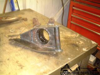
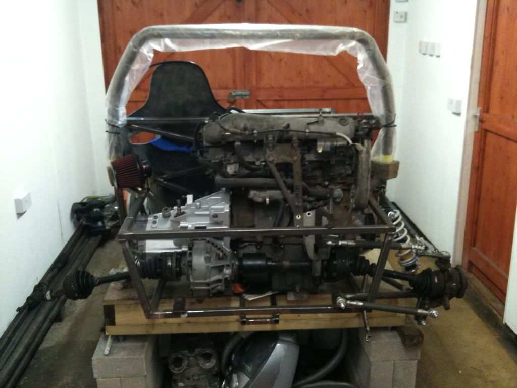
Rear suspension
b14wrc - 15/1/13 at 09:16 PM
Hi all,
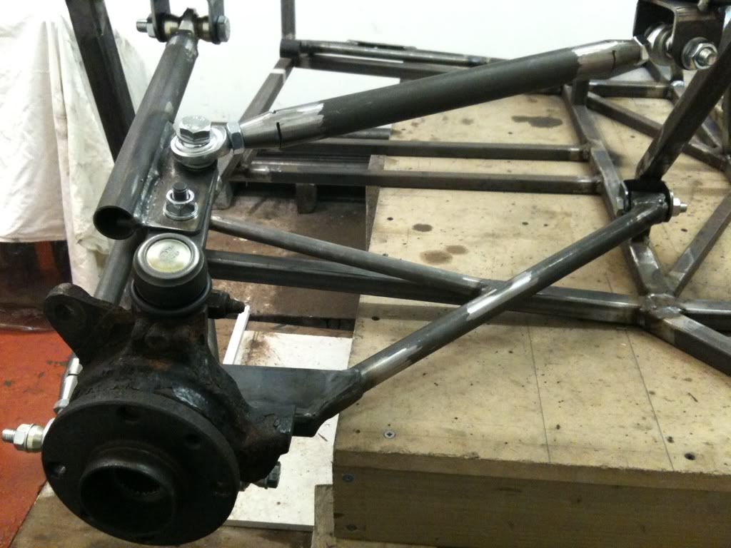
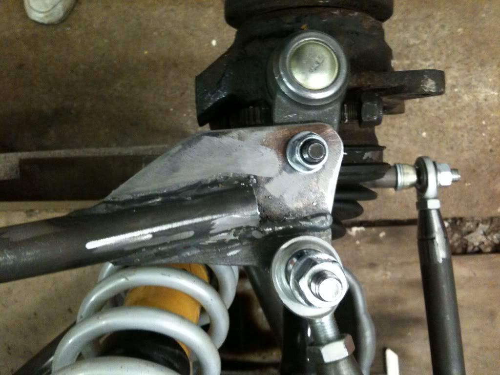
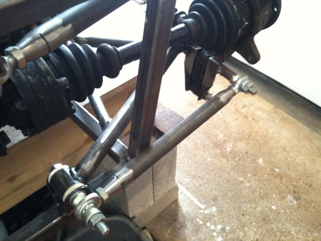
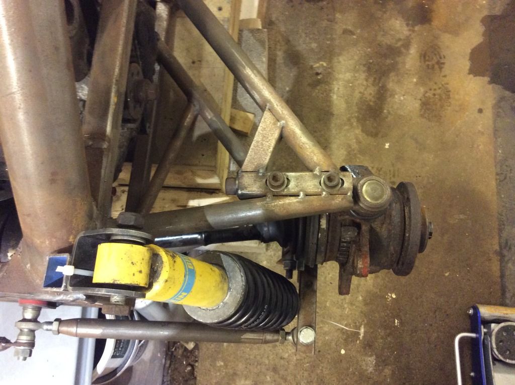
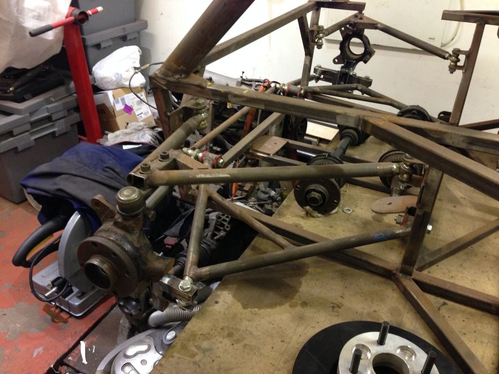
Just wanted to share my progress with rear suspension.
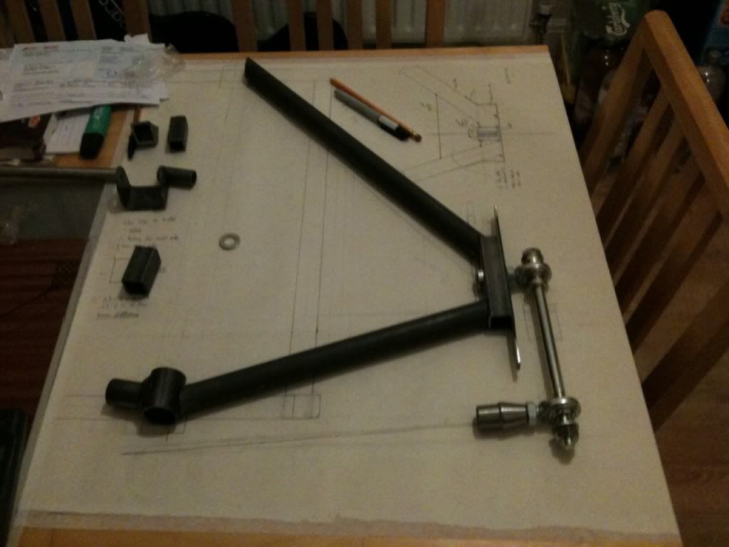
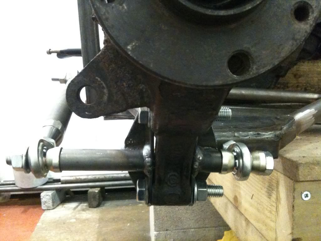
I've played around with the positioning of the A arm and think I've sorted the plung on the drive shaft so should all run smoothly.
Any advice on what initial settings I should use for Camber, Toe?
Rob
jimmyd - 15/1/13 at 09:36 PM
Good work chum but don't be surprised if you get some stick over the orientation of the rod ends. But I guess you know that.
J
Slimy38 - 15/1/13 at 10:15 PM
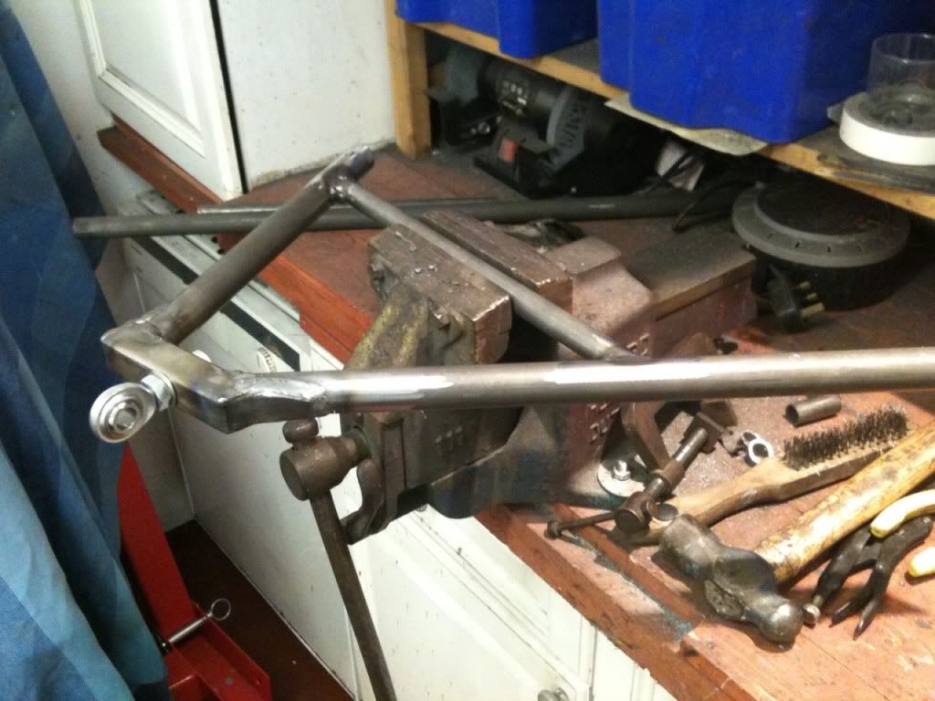
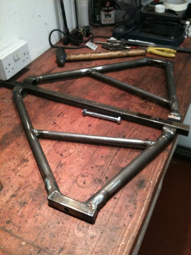
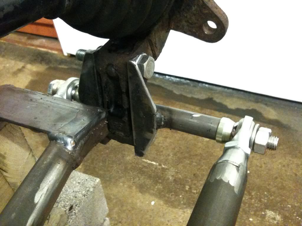
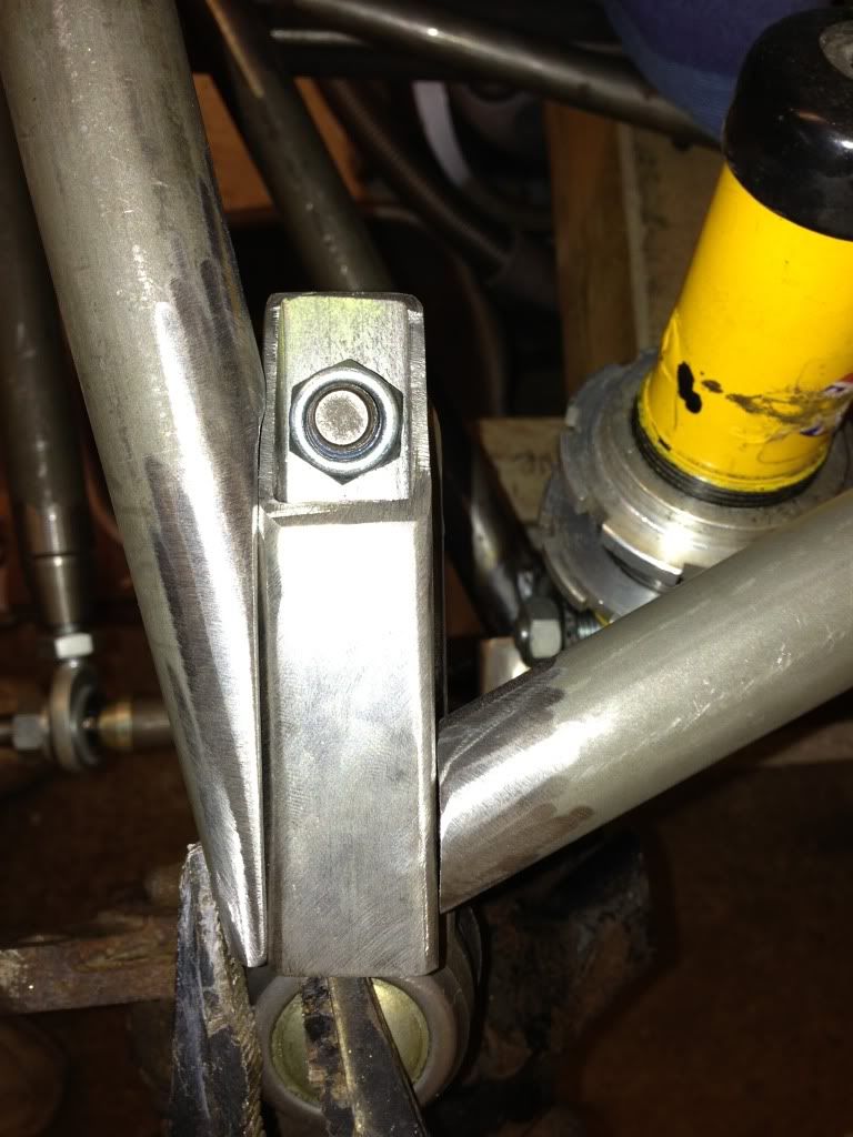
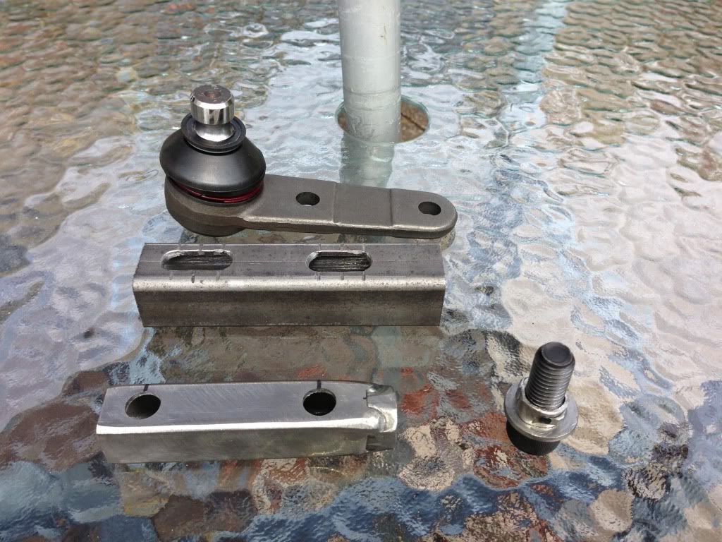
What's your thinking behind the square hollow section to mount the rose joint? Doesn't that leave you with a 4 sided arrangement instead of
a triangle?
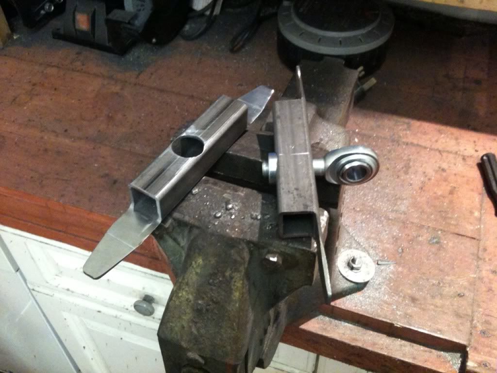
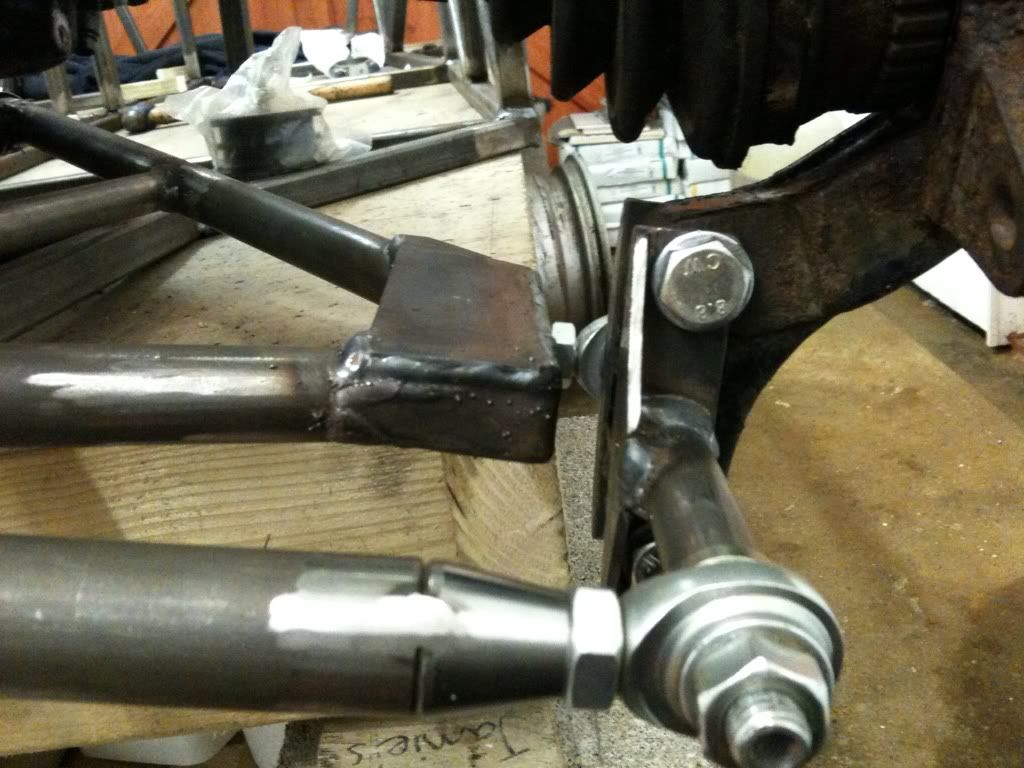
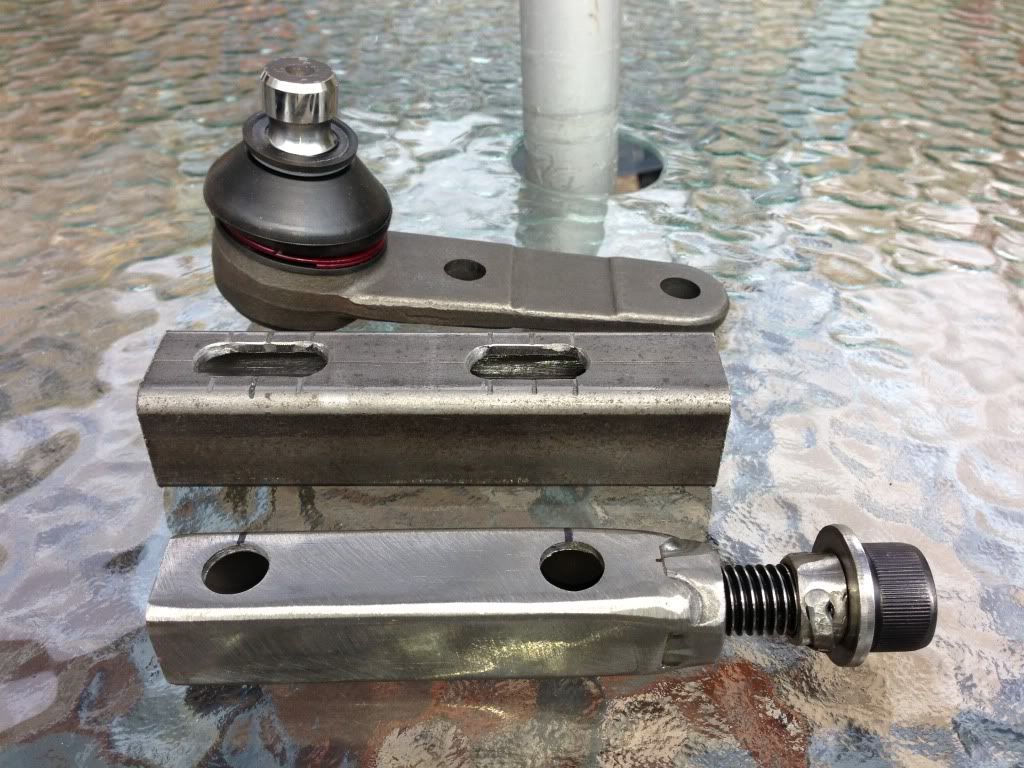
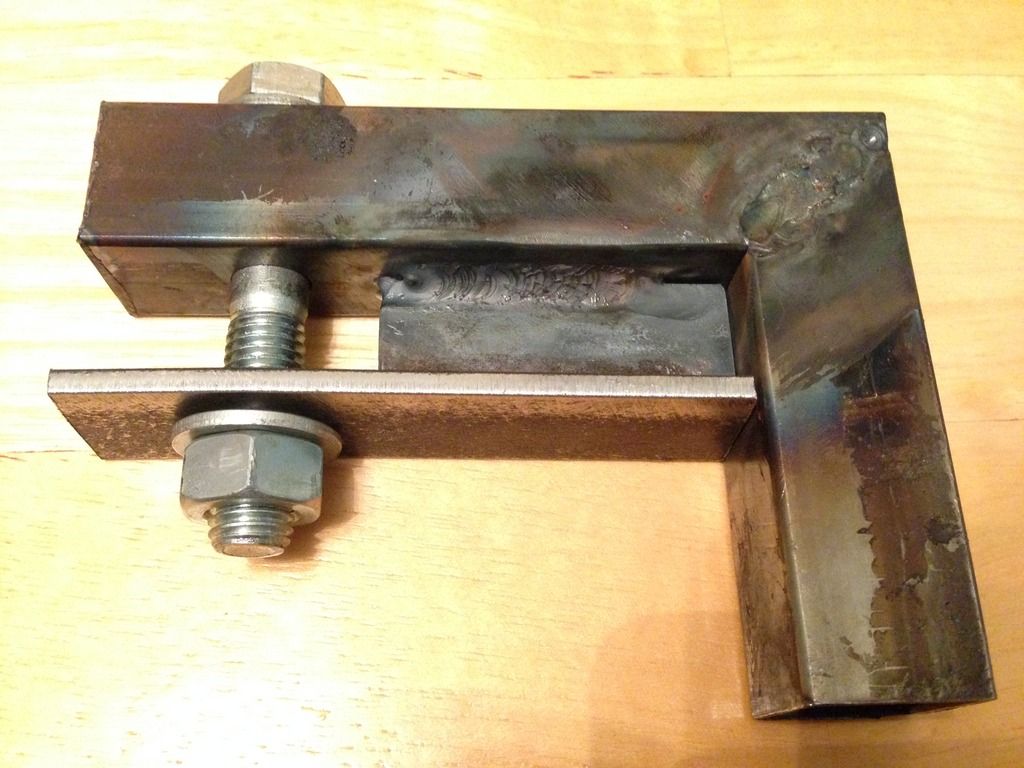
I like the idea of the extra 'tongue' bits both to provide reinforcement and to close off the ends. Did you have much of a gap to fill
between the tongue and the round tube?
mark chandler - 15/1/13 at 10:16 PM
Looks like a very well engineered solid job.
Where are you going to land the shock, infront of the of the half shaft ?
designer - 15/1/13 at 10:54 PM
As said, I don't like the square section to mount the rose joint, it's become a square instead of a triangle.
And have you strengthened the square section where the joint is mounted?
unijacko67 - 15/1/13 at 11:08 PM
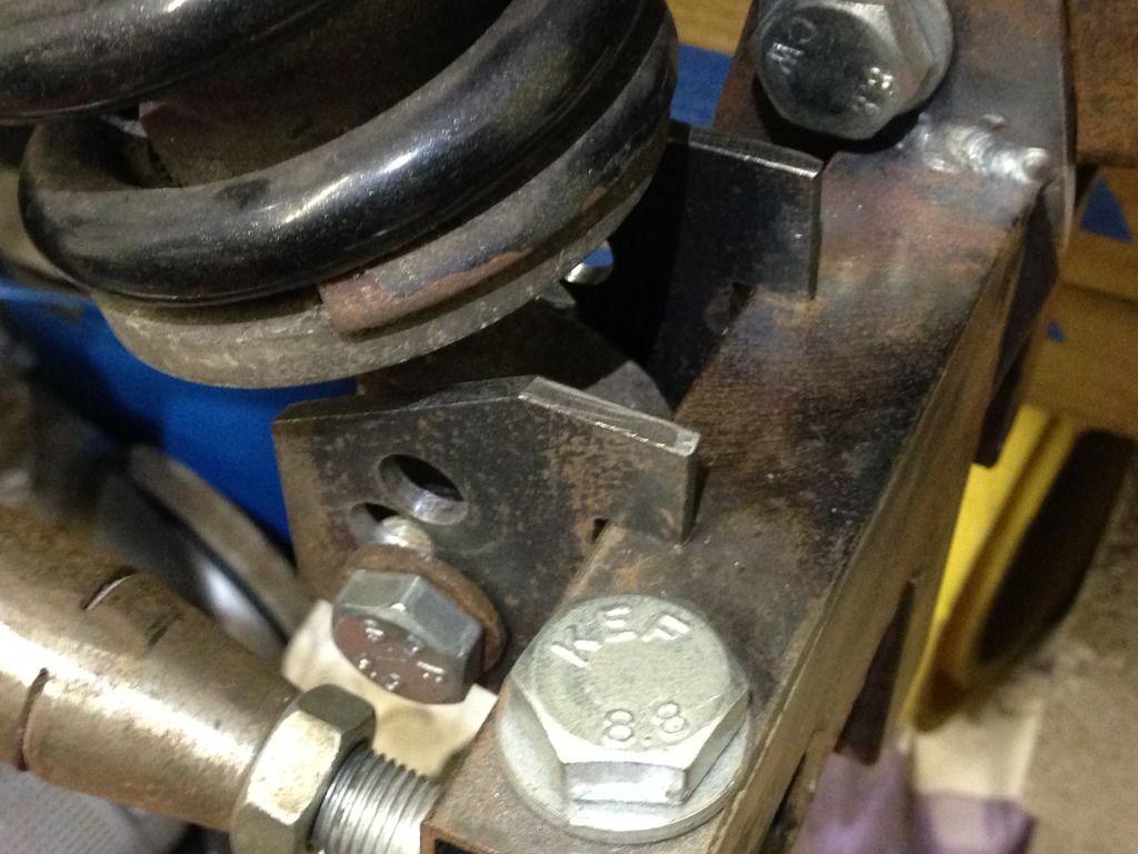
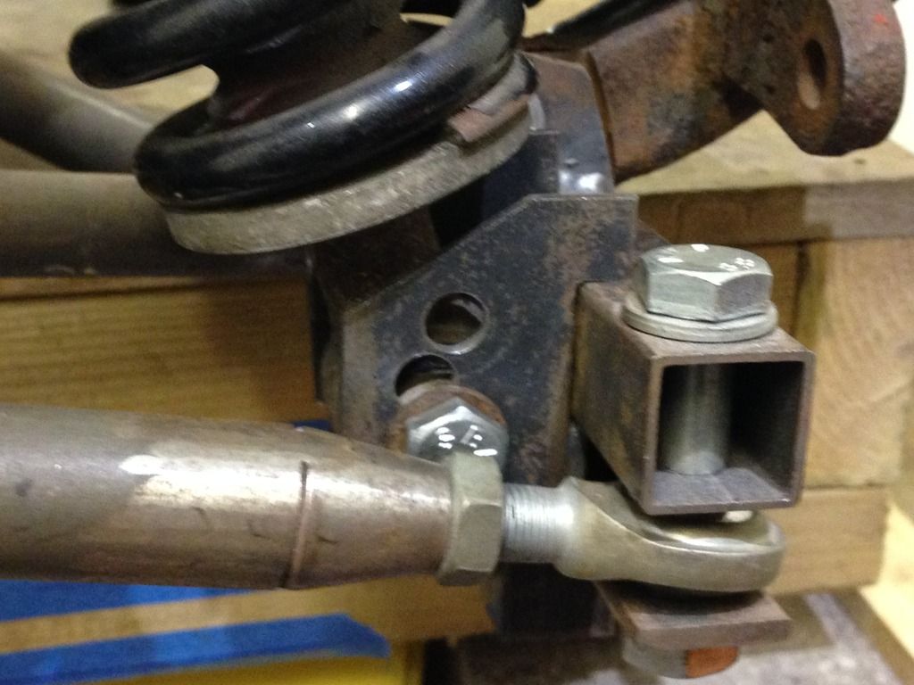
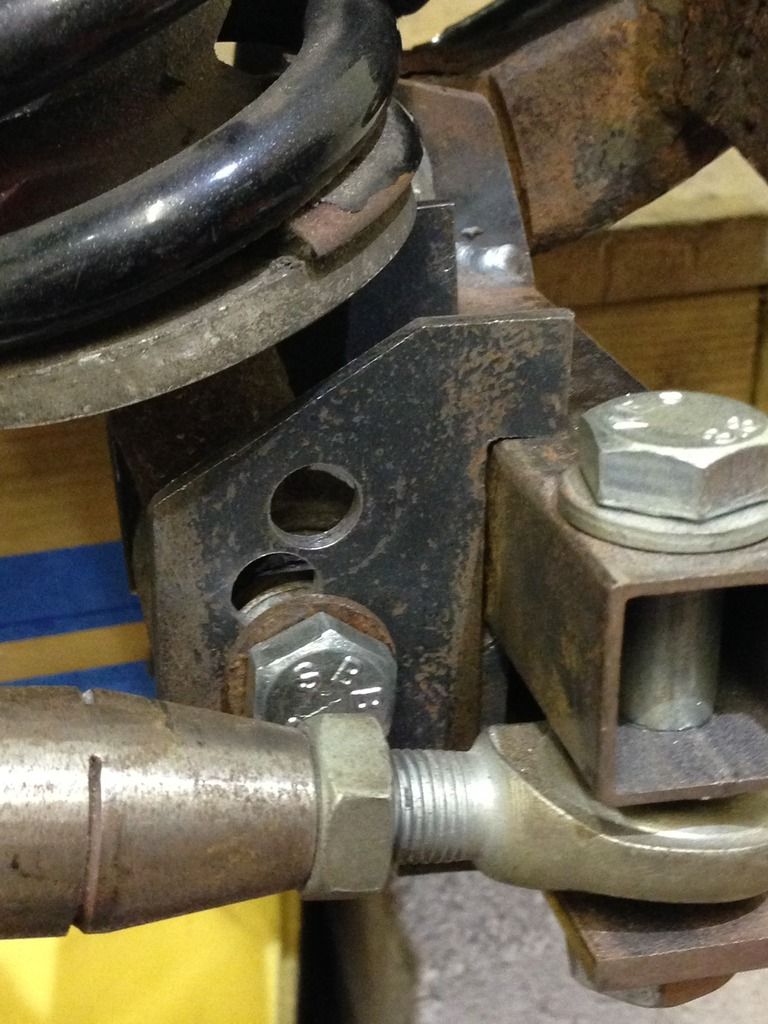
You can see the sleeve in the square section, look's good.
Slimy38 - 16/1/13 at 09:26 AM
quote:
Originally posted by unijacko67
You can see the sleeve in the square section, look's good.
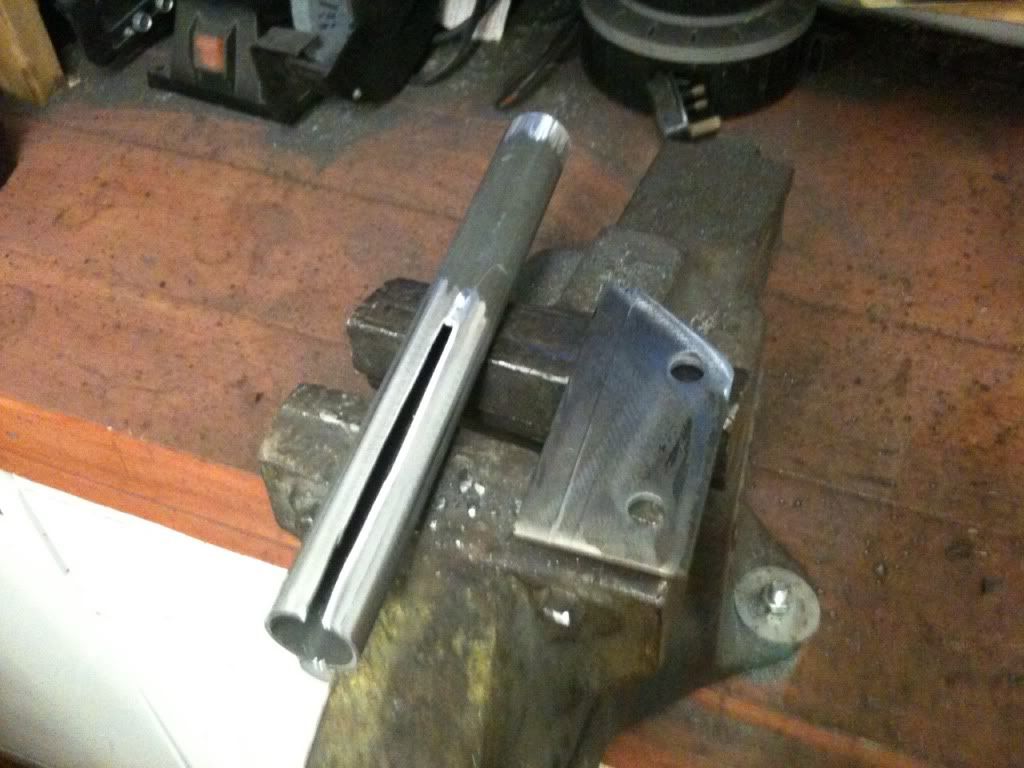
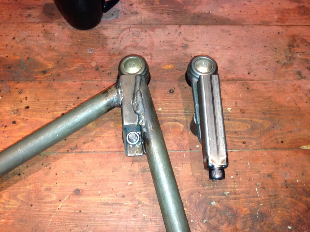
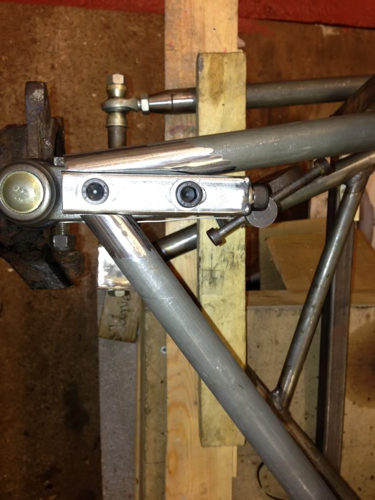
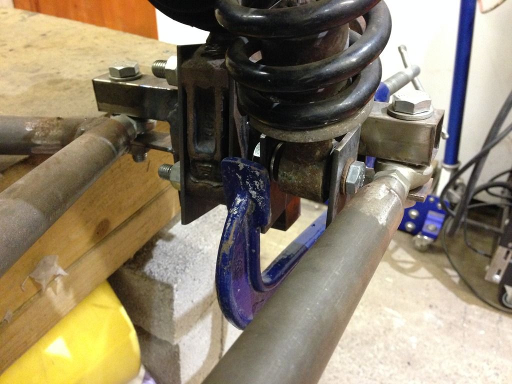
You've got better eyesight than I have, I couldn't see anything other than the rose joint fixing itself? The picture of the two SHS sections
laid on the vice shows a rose joint partially fitted and I can't see any sleeve?
Unless I don't know what I'm looking at (which is extremely likely!).
phelpsa - 16/1/13 at 10:11 AM
quote:
Originally posted by Slimy38
quote:
Originally posted by unijacko67
You can see the sleeve in the square section, look's good.
You've got better eyesight than I have, I couldn't see anything other than the rose joint fixing itself? The picture of the two SHS sections
laid on the vice shows a rose joint partially fitted and I can't see any sleeve?
Unless I don't know what I'm looking at (which is extremely likely!).
[Edited on 16-1-13 by phelpsa]
Slimy38 - 16/1/13 at 11:19 AM
Yeah, that's the picture I'm thinking of. But I can't see a sleeve? If anything, the angle of the rose joint compared to the SHS
suggests that there is nothing inside the steel keeping it straight.
phelpsa - 16/1/13 at 11:52 AM
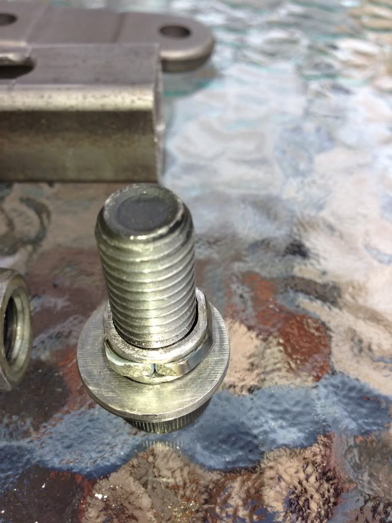
The larger diameter silver bit hanging out the back of the tube is a threaded insert about an inch long and 3/4 diameter by the looks of it. That is
welded in and the rod end is screwed into it.
Slimy38 - 16/1/13 at 12:48 PM
Aha, now I understand. I'm guessing when the picture was taken it was in place but not welded (no trace of filler or heat change on the steel).
Thanks for pointing it out to me, I thought I was missing something obvious! 
b14wrc - 16/1/13 at 12:49 PM
Hi all,
Thanks for the comments. To answer some of the questions:
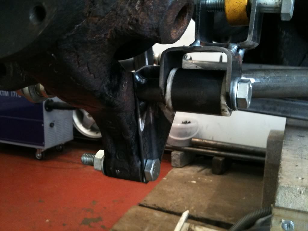
1. Yes, there are inserts for the rose joints, can you not see them? They are not welded yet but fit into the back of the square section. Thanks
Phelpsa for helping with pointing this out to those who missed it, I�m glad you understood.
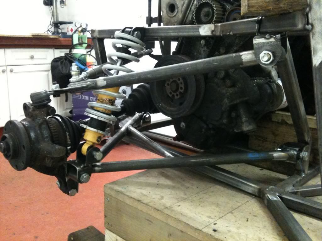
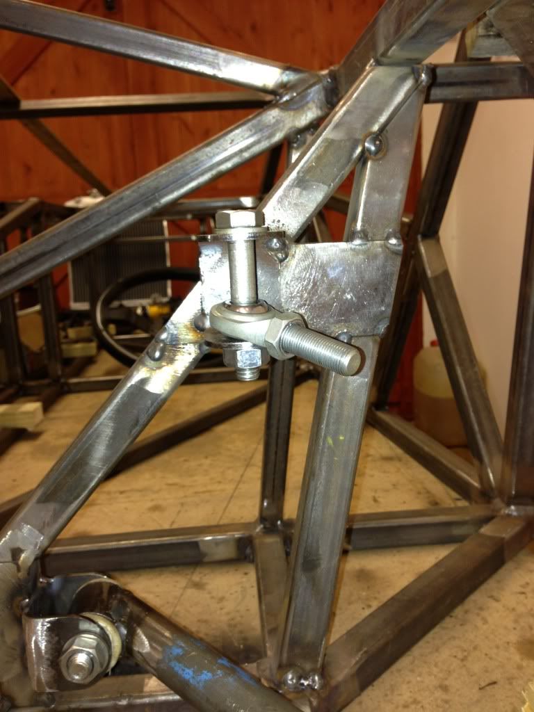
2. The reason for the square section was a) to help with keeping the rose joint square when the locking nut was tightened, b) the shock will be
mounted to it in front of the half shaft.
3. I liked the tongues, it seemed a good way to reinforce the butt joints. I basically tack welded them in place and hammered them down using the
round part of my hammer, there was a slight gap, but I did two runs of weld to completely fill the V between the round and flat tube. Worked well.
4. I also plan to add a piece of 50mm wide 3mm thick flat bar on the underside of the arm to reduce the flexing as it is not a triangle or I may add
another tube from the cross member to the corner where the shock will fit.
Rob
Slimy38 - 16/1/13 at 02:26 PM
quote:
Originally posted by b14wrc
1. Yes, there are inserts for the rose joints, can you not see them? They are not welded yet but fit into the back of the square section. Thanks
Phelpsa for helping with pointing this out to those who missed it, I�m glad you understood.
Yep that was entirely my bad, I had no idea what I was looking at! I just thought it was a big washer.
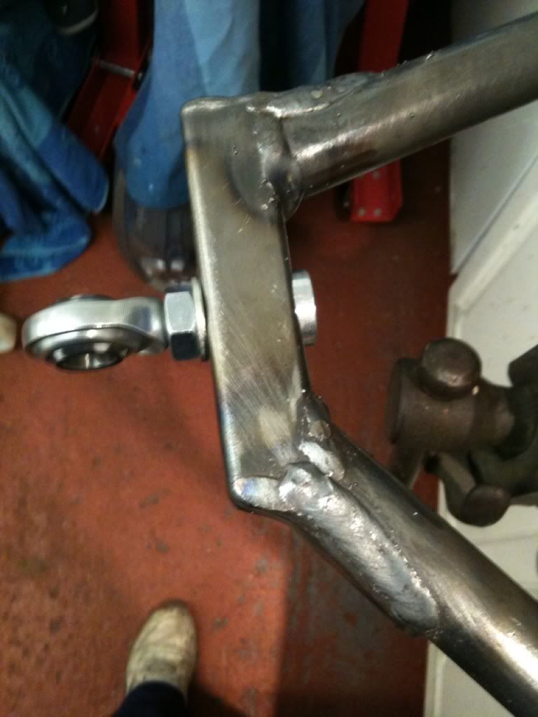
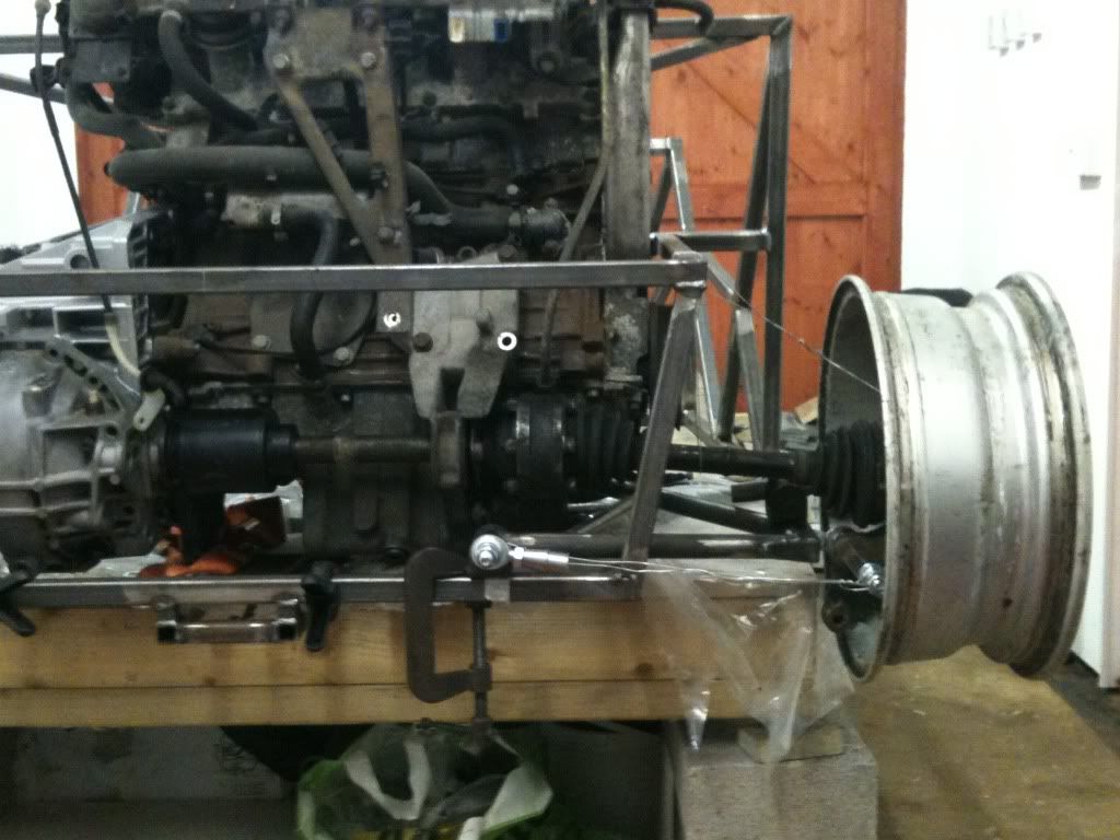
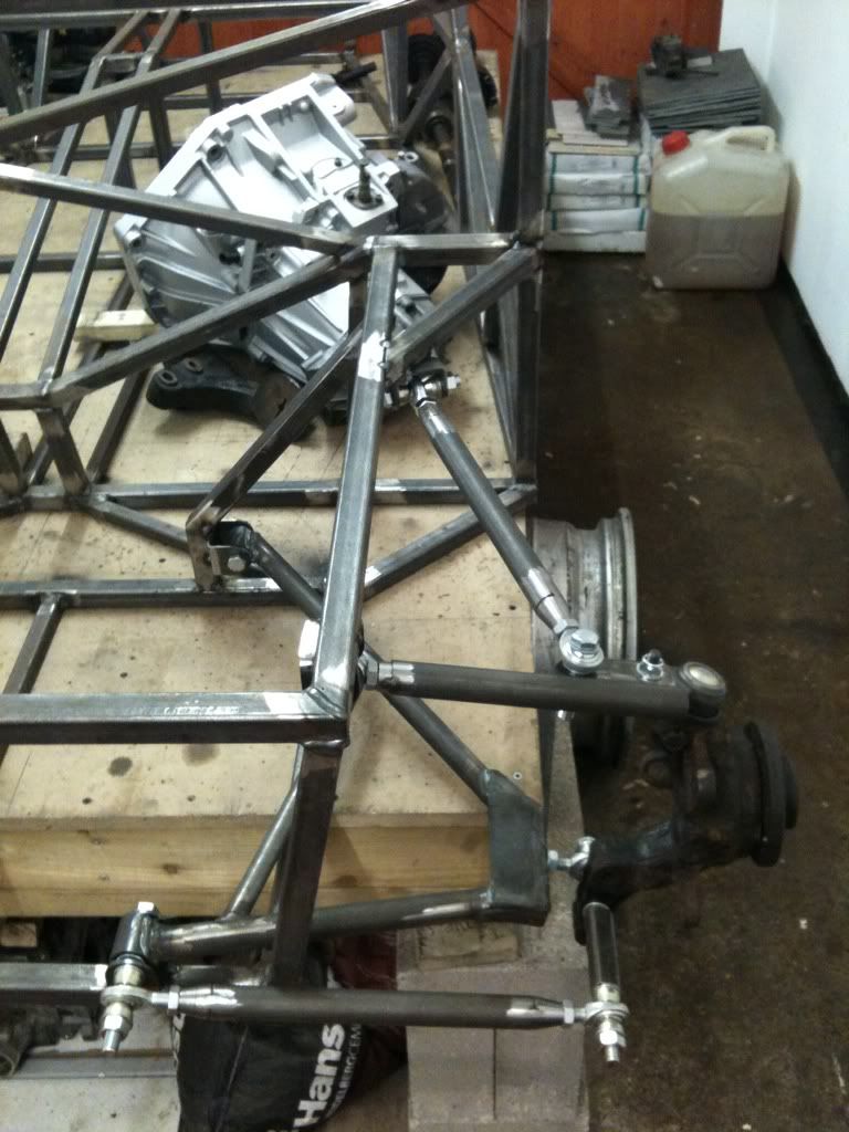
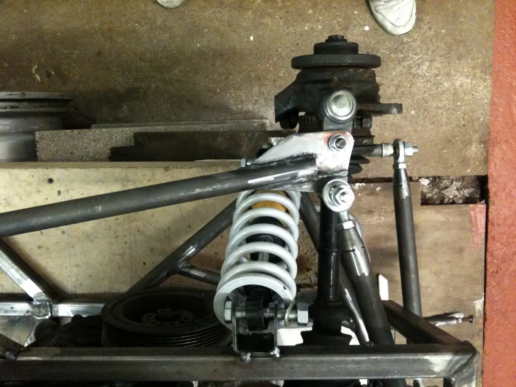
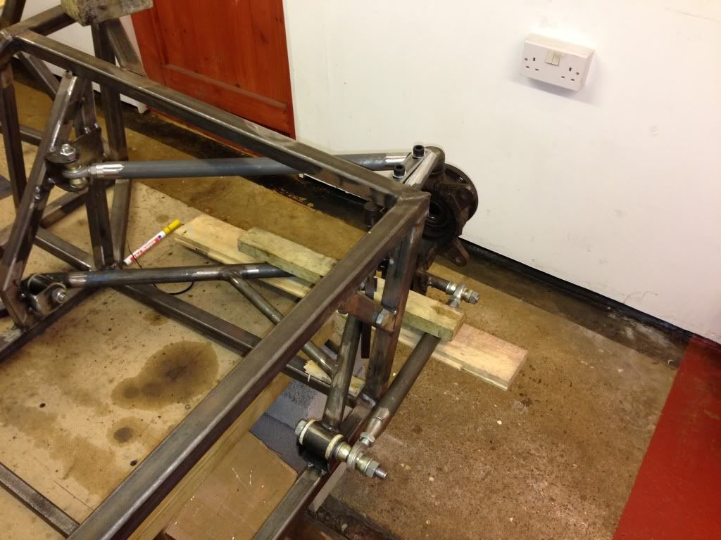
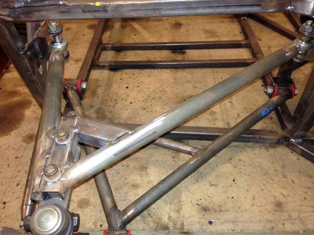
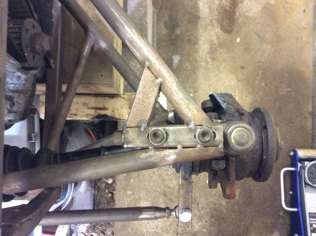
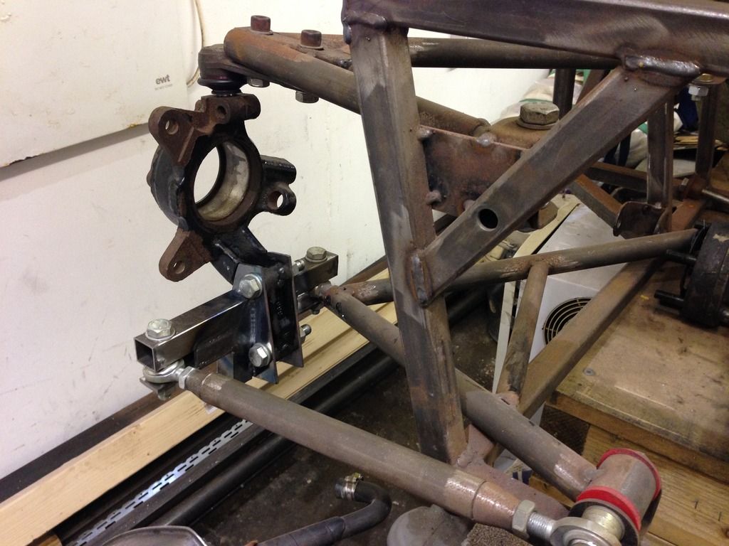
b14wrc - 19/1/13 at 08:52 PM
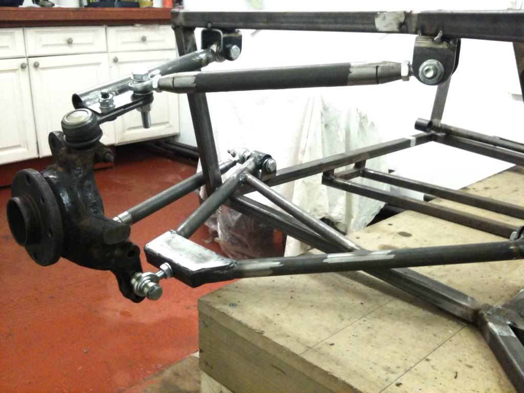
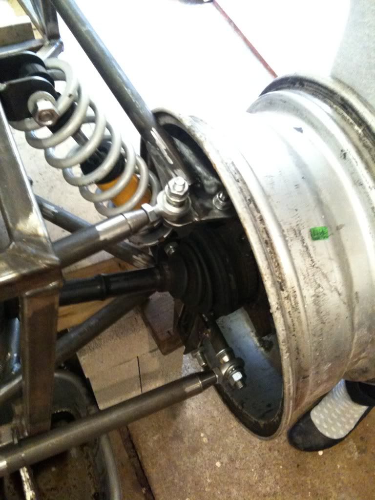
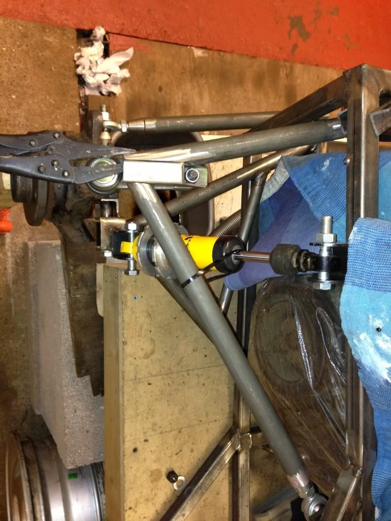
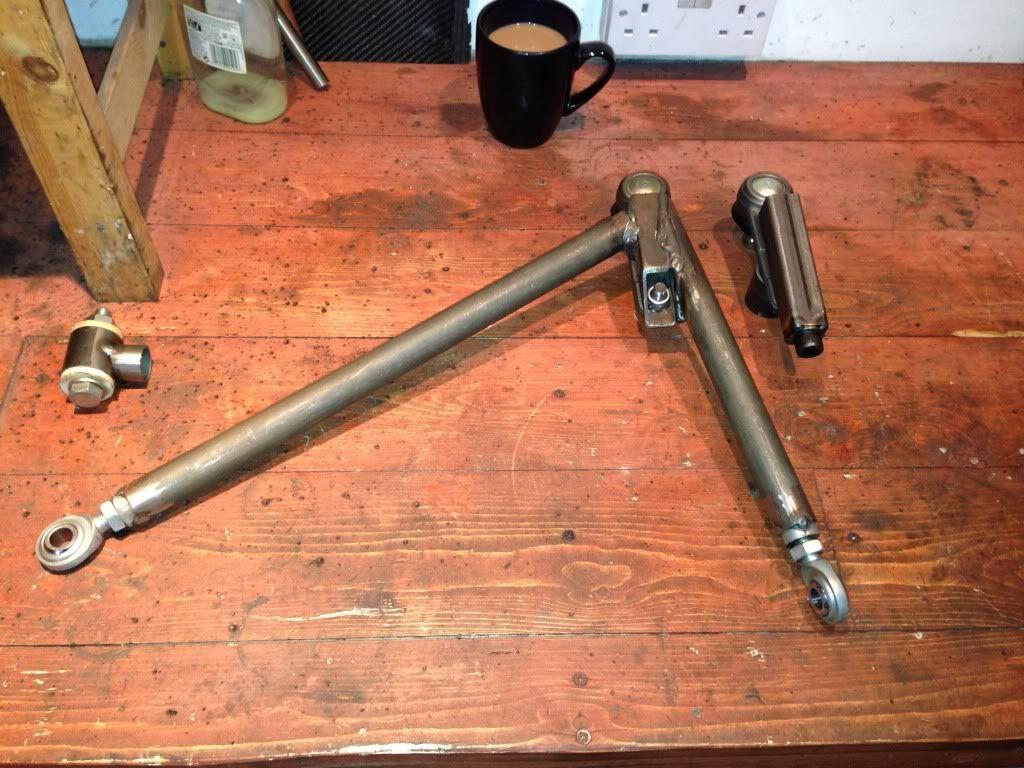
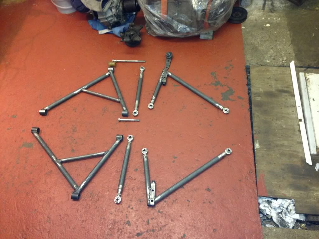
Top arm construction:
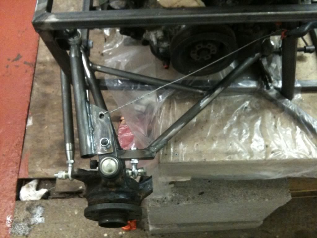
Still a bit of work to do, but when I tested the travel the camber seemed to stay fairly constant, if any thing it gained a little positive camber at
full compression. Assume this is normal?
Need a link rod to replace the wire!
Rob
maccmike - 19/1/13 at 11:28 PM
looking great
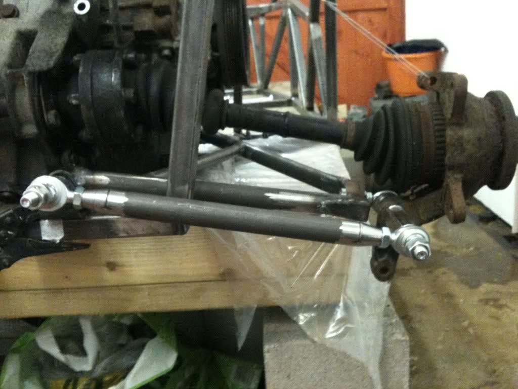
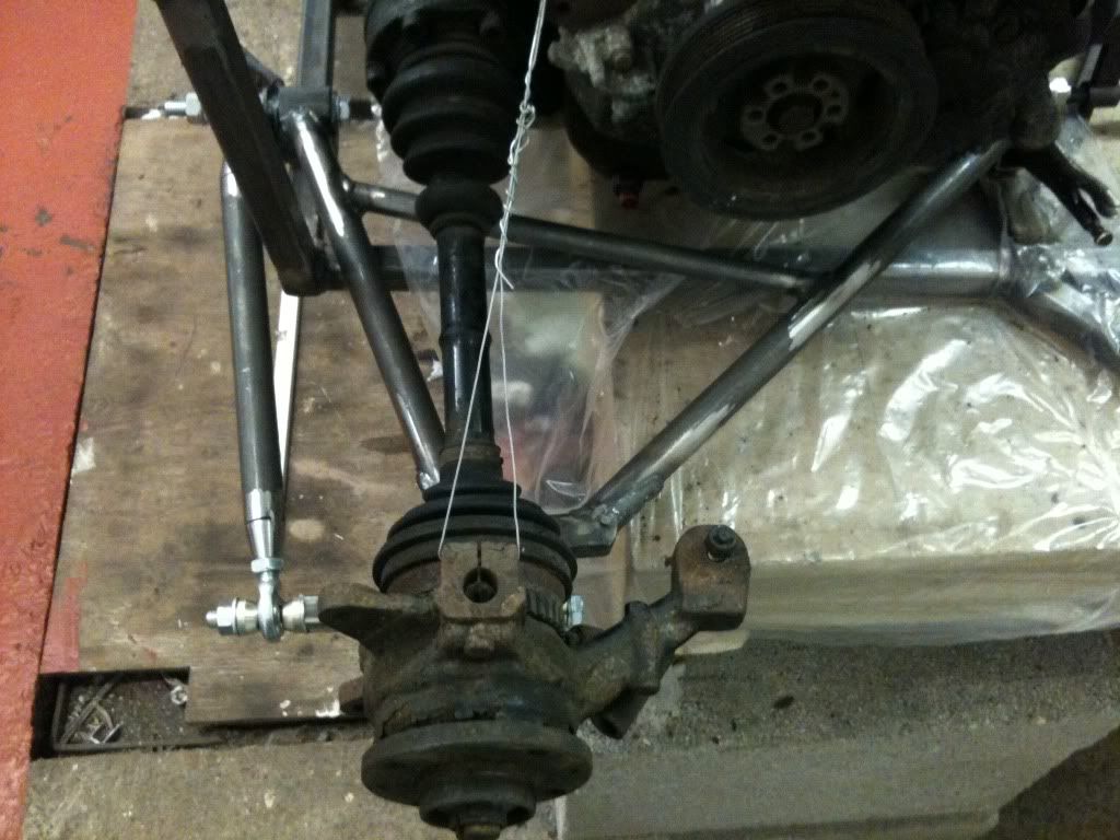
b14wrc - 26/1/13 at 07:59 PM
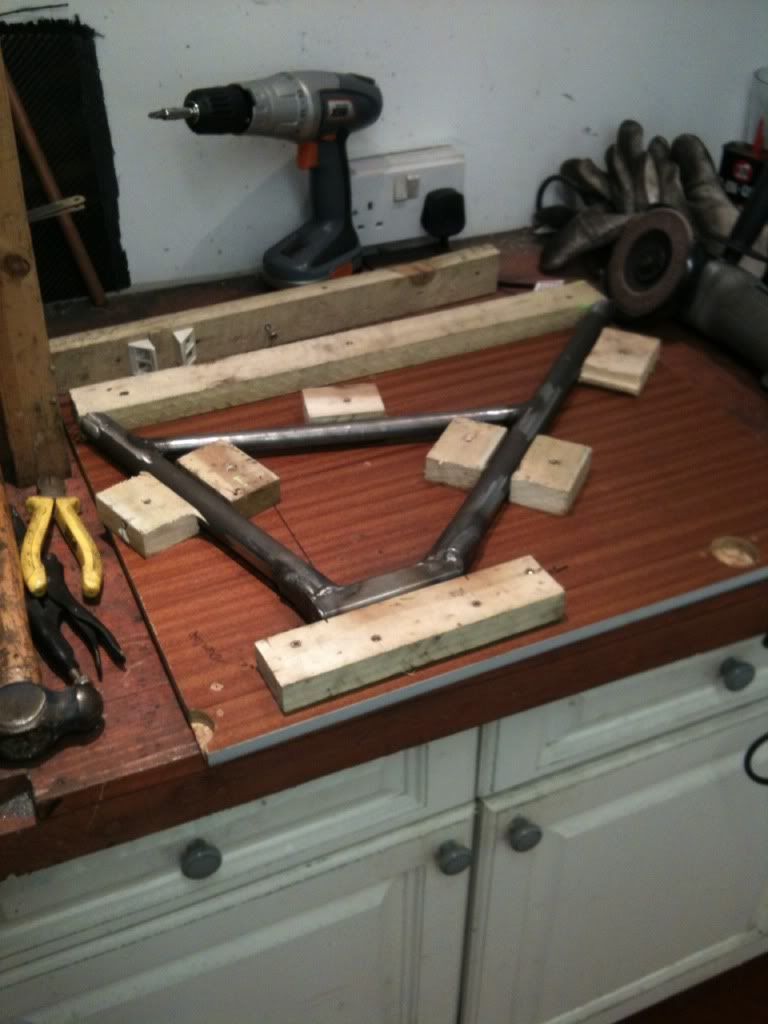
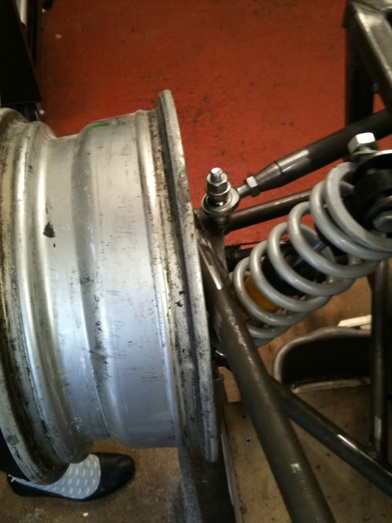
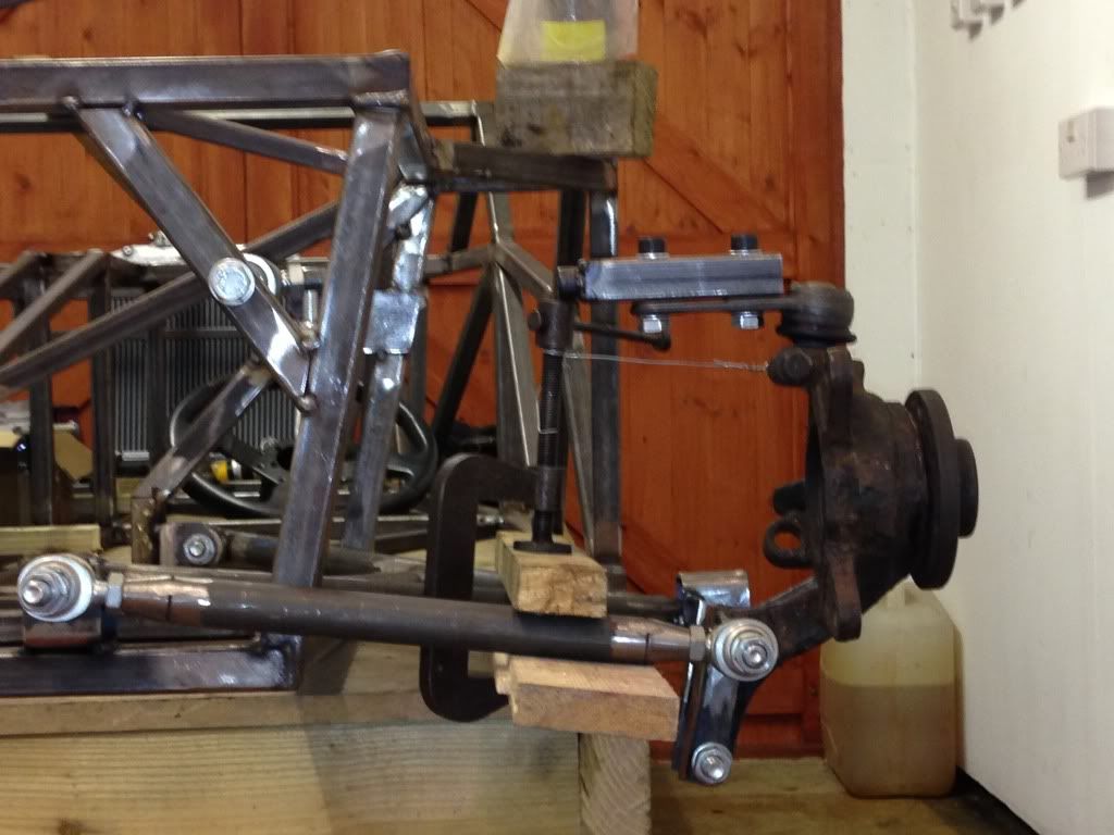
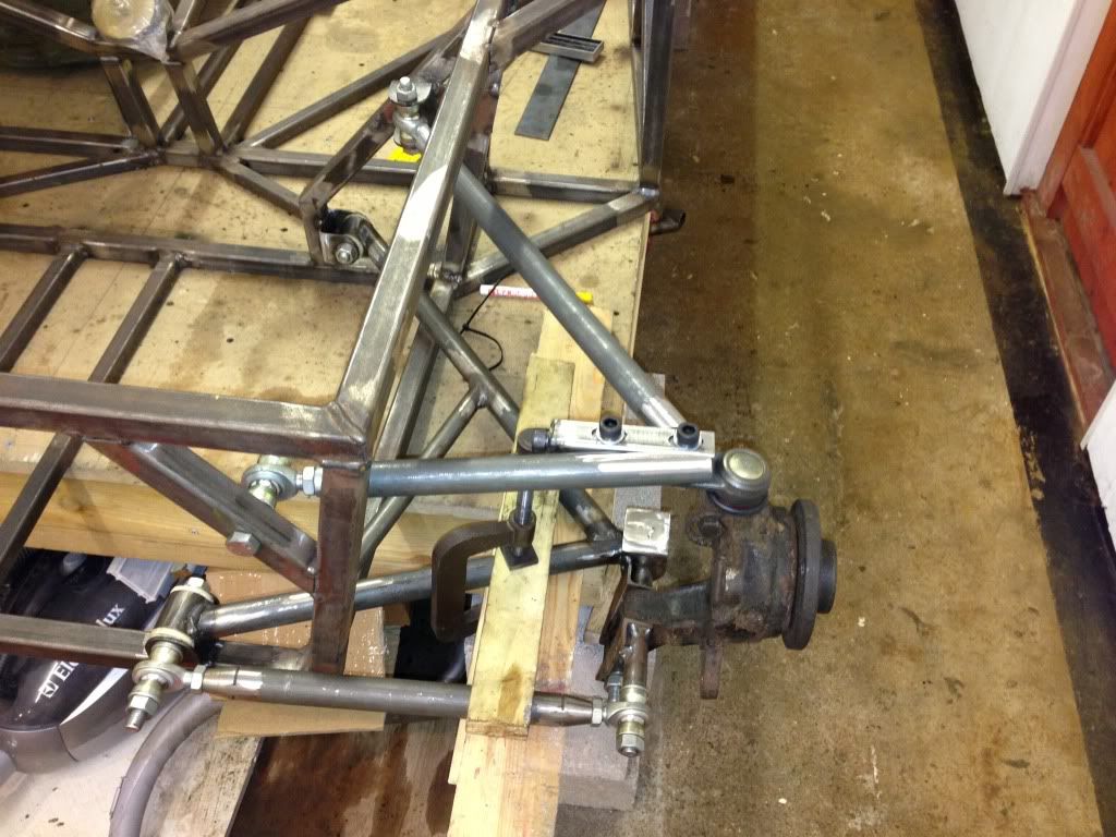
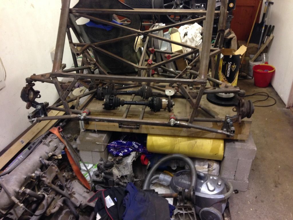
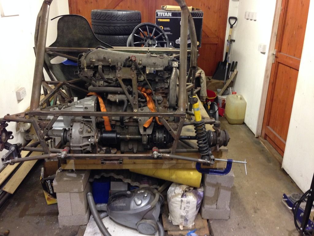
Just an update on this weekends work:
Made the second wish bone
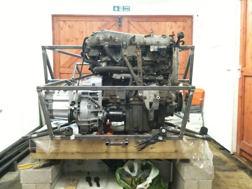
And the wire has gone;
Got a few changes to make, top arm is too long, and then need to cast the PU bushes, not made the mould yet though!
These cars take a lot of work! Pretty pleased with the way it's coming to gether, hope engine fits in still.
Rob
TAZZMAXX - 26/1/13 at 09:37 PM
quote:
Originally posted by
b14wrc
Still a bit of work to do, but when I tested the travel the camber seemed to stay fairly constant, if any thing it gained a little positive camber at
full compression. Assume this is normal?
I'm no expert on this but I do have a pile of books on suspension design that I'm ploughing through at the moment. I would have thought that
positive camber would be undesirable as, when coupled with body roll, it will increase and reduce tyre contact patch. The angle downwards on your top
arm looks to exceed the angle on the lower arm which is what is creating your positive camber increase. If it were level (top arm) with the lower arm
angled down will will go to slight negative whereas angling the top arm upwards (lowering the mounting points) will increase your negative camber
which would be more desirable. It's a really interesting subject that you really need to get to grips with if you want your car to handle
well.
Good on you for what you've done so far, it looks good and there's always more than one way of doing things. Don't take the above as
criticism but I think you could do some simple alterations to make it loads better.
Cheers.
[Edited on 26/1/13 by TAZZMAXX]
MikeRJ - 26/1/13 at 10:44 PM
The entire corner weight is being supported by a single rod end in a bending moment. I hope you have done your sums!
Grimsdale - 27/1/13 at 09:57 AM
why not mount the top arm to the outer bolt on the ball joint? then you are reducing the bending moment on the top wishbone. It does not look right as
it is.
Doug68 - 27/1/13 at 10:07 AM
quote:
Originally posted by MikeRJ
The entire corner weight is being supported by a single rod end in a bending moment. I hope you have done your sums!
What he said, where is the shock going to attach? To the top arm, bottom or the upright directly?
Also it looks as if directional control of the rear wheel is dependent on the square tube coming away from the bottom of the upright being held tight
up against the upright. I think the leverage at this point would huge say when you hit a pot hole or something. It looks like you cut of the
steering arms from the uprights? I think it would have been better to have used those and dialed out the bump steer than the method shown. This is
how I did mine.
Positive camber is also to be avoided, you want negative when you start and more negative at full bump.
I hope the the above is take in a positive way, I've been through all this myself so I know how much effort it is.
b14wrc - 27/1/13 at 12:35 PM
Morning all,
I made a mistake when I quoted positive Camber, I had mixed up pos and neg. it actually gains slight negative. I understand contact patch and roll,
that's why I was asking, I think I know the theory, just wanted other people's opinions.
Ok, a few comments, good, I was after some help. First thing though, I think your all looking at the wrong photos, the one that's quoted is not
the latest. I added new ones yesterday, please note the upper arm position has moved.
The square tube is only temporary. I am going to make a proper bracket that will bolt to the original macpherson strut holes. 20mm tube with a
stainless crush tube inside.
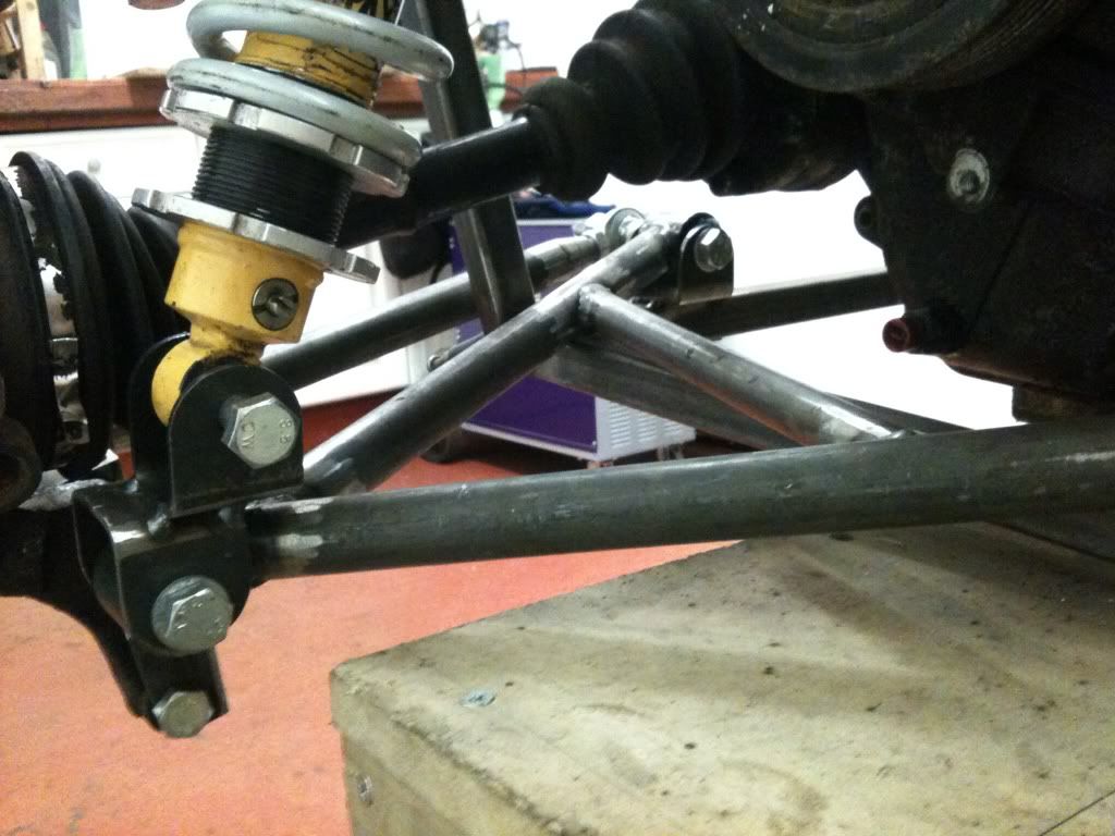
The single rod end corner weight? How is this, I might have missed something there? I have a pair of rod ends on the outer lower arm, the load will be
distributed through them both wont they?? Each are rated to 4 tons, so the load to failure would be 8ton pressure if all the car was hanging on the
one wheel at 3g.
Shock will be mounted to the steel plate at the end of the A arm.
I have also read many books, but it's a lot easier to build an ideal system when you don't have the engine to work around, think I have a
fairly good solution considering.
Yes, I cut the steering arms off. I didn't want to use them and thought the mojo uses this principle so - so would I.
Regards, Rob
Doug68 - 28/1/13 at 12:29 PM
Hi b14wrc,
I assume that the shock will mount to the lower A arm then?
The rod at the rear of the A arm basically cannot be taking any of the bump load if there is not something for it to react against such as a spring.
This means all the bump load has to be transmitted through the rod end into the A arm for the spring to work against.
The load values quoted for a rod end are acting axially down the shaft i.e. in your case trying to pull it out of or push it into the A arm. The load
that going into the road end though is trying to bend the end of the rod end off of the shaft.
You might want to read: http://www.aurorabearing.com/pdf/rod-ends.pdf
If you google "rod end in bending" you'll get a good few results to mull over and there's been one or two heated debates on this
forum on the subject in the past.
On the rear wheel toe control method if you've got a working example to follow, then I'll shut up on that one 
b14wrc - 29/1/13 at 12:28 PM
Hi Doug 86,
Yes, the shock is mounting to the steel plates that are welded to the top side of the A - Arm and bolt to the top rail in the engine compartment.
I see what you are all saying about the rod end, I am thinking of replacing it with a piece of tube and having a bush there instead.
Yes, my suspension is based on the idea the Sylva Mojo uses. It actually works quite well.
Rob
Fred W B - 29/1/13 at 03:21 PM
You can remove the concerns with the rod end in bending if you attach the coilover to the upright.
Cheers
Fred W B
daviep - 29/1/13 at 03:55 PM
quote:
Originally posted by Fred W B
You can remove the concerns with the rod end in bending if you attach the coilover to the upright.
Cheers
Fred W B
I think the driveshaft will probably be in the way?
Cheers
Davie
Fred W B - 29/1/13 at 04:22 PM
Yes, it would need some sort of offset bracket off the 2 holes in the bottom of the upright, or make a complete new upright around the bearing cup.
Cheers
Fred
[Edited on 29/1/13 by Fred W B]
b14wrc - 30/1/13 at 12:22 PM
Humm, i wonder if i could make a baket to bolt the shock to the hub, the drive shaft would get in the way, but if i coud use a spacer, it might
work......
britishtrident - 30/1/13 at 08:11 PM
quote:
Originally posted by b14wrc
Humm, i wonder if i could make a baket to bolt the shock to the hub, the drive shaft would get in the way, but if i coud use a spacer, it might
work......
That would result in a pretty big twisting moment on to the hub and the way it appears to me in a number of ways the whole concept is already
close to or on limits of what will safely hang together.
I advise stop fabricating for a few days and have think about the direction this layout is taking you, and consider the conventional path of using
uprights based on Sierra "ears" .
As an alternative to wishbone layouts used on Sierra based Locosts you might also like to look at the rears suspension layout used on late 1960s
F1 cars and sports racers for example the Lotus 33 or 49 any of Len Terry's cars of that era.
b14wrc - 31/1/13 at 12:03 PM
Thanks for the input.
Could you explain to me why my design is already on the limits? As far as i can see, its fairly similar to any other.
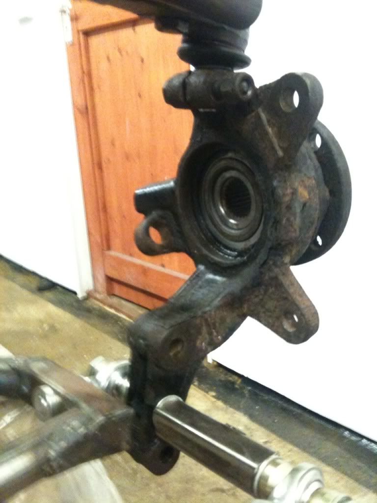
As for using the sierra hubs, which will give me a massive issue with the fiat hubs, fiat hubs have 26 splines on the drive shaft and fords run 25 or
27 as far as i have looked. Plus the length probably will be all wrong. I am not really sure what addvantages i would get.
I am looking for constructive criticism with this as I�m not a mechanical engineer.

Rob
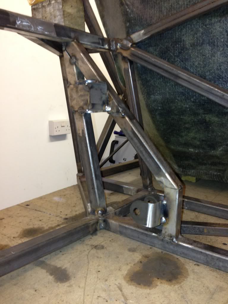
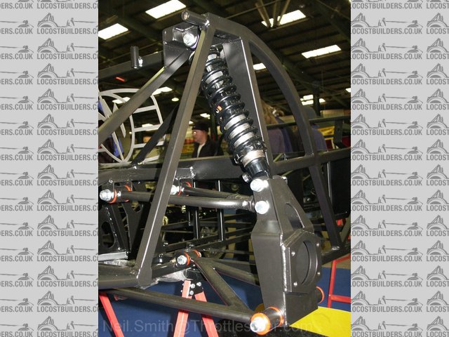
mark chandler - 31/1/13 at 12:29 PM
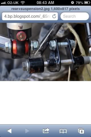
This is my rear setup, no issues in maybe 5 years, only tracked on slicks so it does get a pounding.

Although not clear in the picture the bone spans both sides of the hub with a single bolt going through the hub with a rose joint either side
(it's a mirror image) with a diagonal to brace the bone.
I have to run heavy springs due to the working ratio.
My load is spread across 2 x rose joints and I adjust by twiddling the two lower ones, I guess the concern is that if you land the shock on the bone
then all the weight will be taking on only 1 rose joint so you will have a lot of force here.
If you land the shock on the hub then all the weight is directly on the hub so the bone is just spacing out the hub and taking the turning torque.
The latter is preferred but build restrictions change the game, in my case I am happy although this is based upon if it looks right it's probably
right without any calls.
Regards Mark
[Edited on 31/1/13 by mark chandler]
britishtrident - 31/1/13 at 10:35 PM
The aspect that most concerns me on the design is the bolt on arrangement that controls the toe I really can't see that surviving even light
contact with a kerb.
As somebody wisely suggested earlier you have to think in terms of triangles not squares so that the forces within the wishbone or other part
should act along its axis either compress or stretch a tube not bend it and avoid nasty bending stresses don't occur at the corners.
Another problem is you say you have positive camber as the suspension compresses as would due to body roll -- the outside wheels in a corner
should have camber gain ie increasing negative camber to compensate for body roll. Using an upside down strut bottom isn't the best start to
achieve this.
Mark Chandler's rear end is nice example of typical accepted practice.
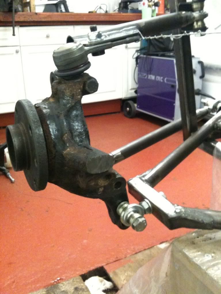
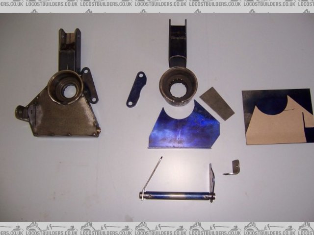
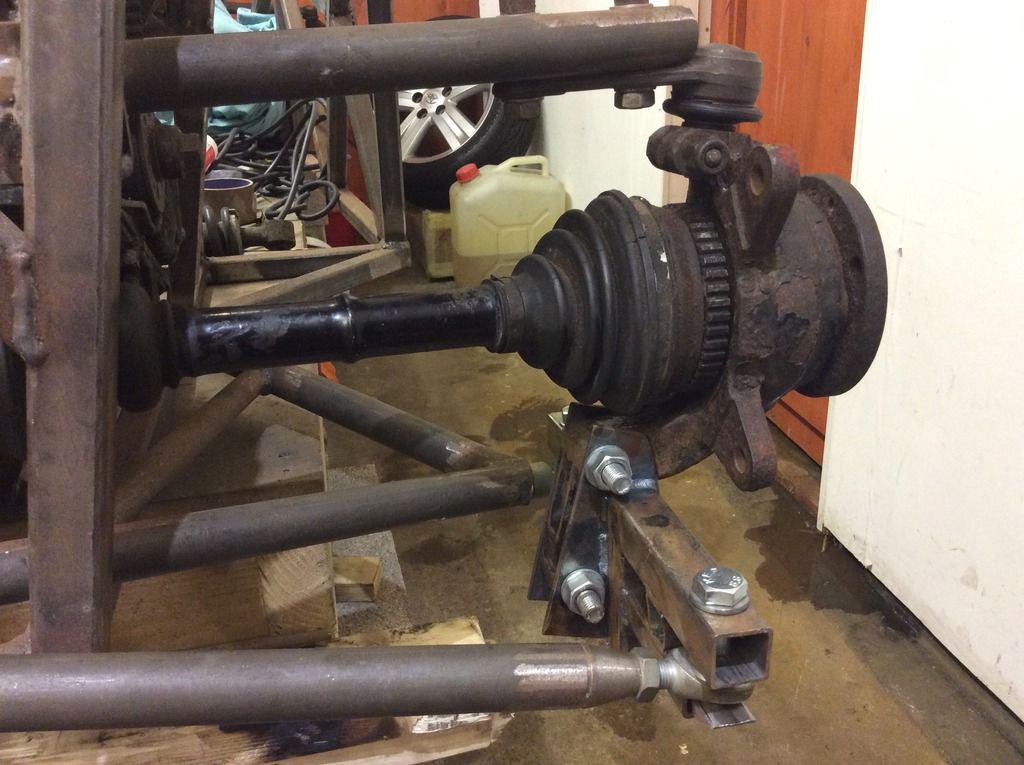
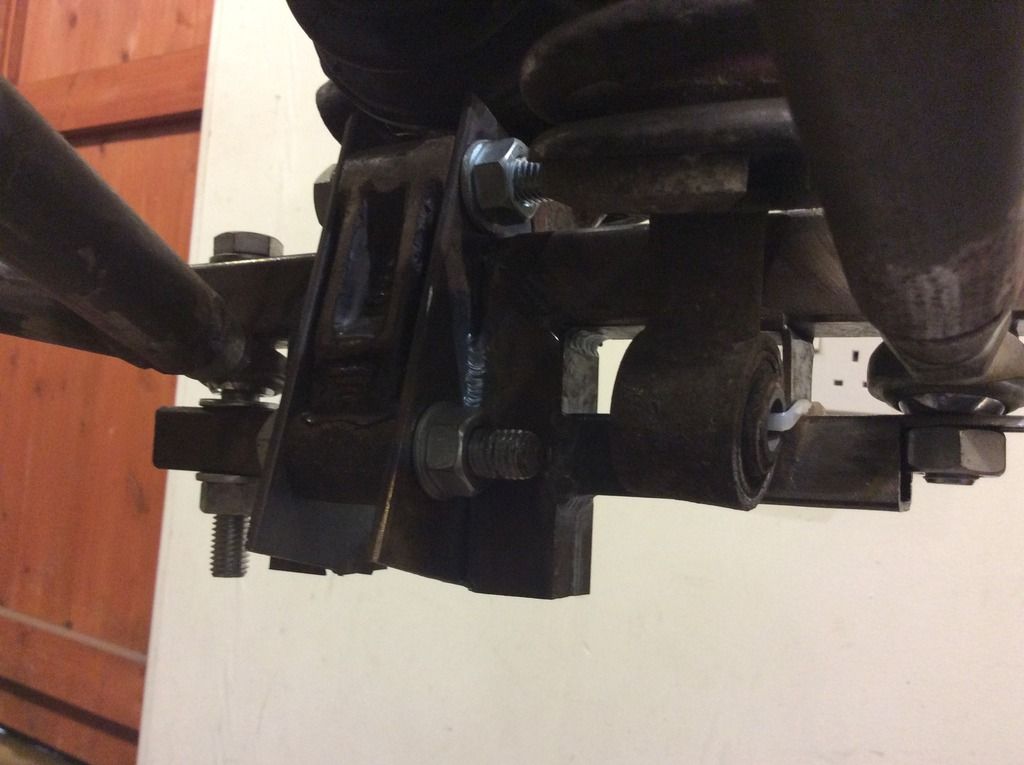
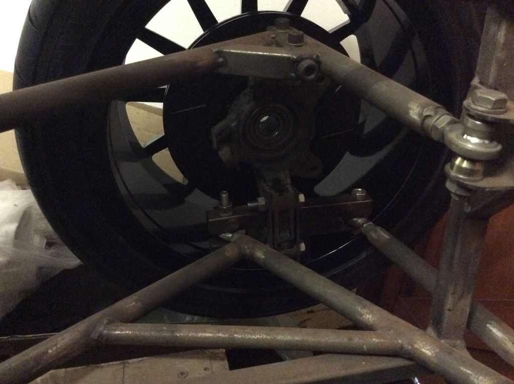
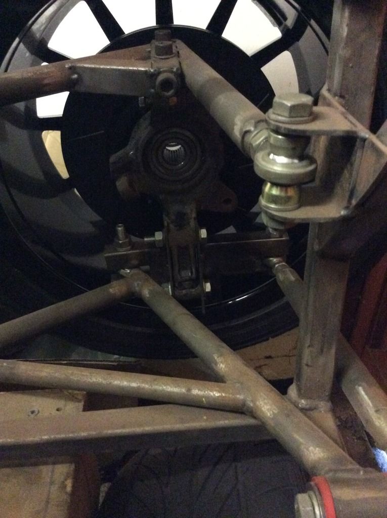
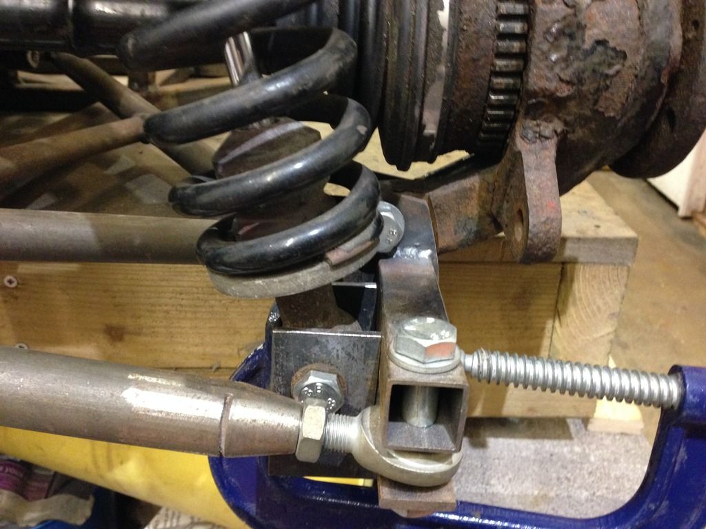
b14wrc - 2/2/13 at 02:19 PM
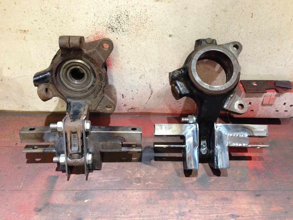
Hi,
Thanks for most of the comments guys.
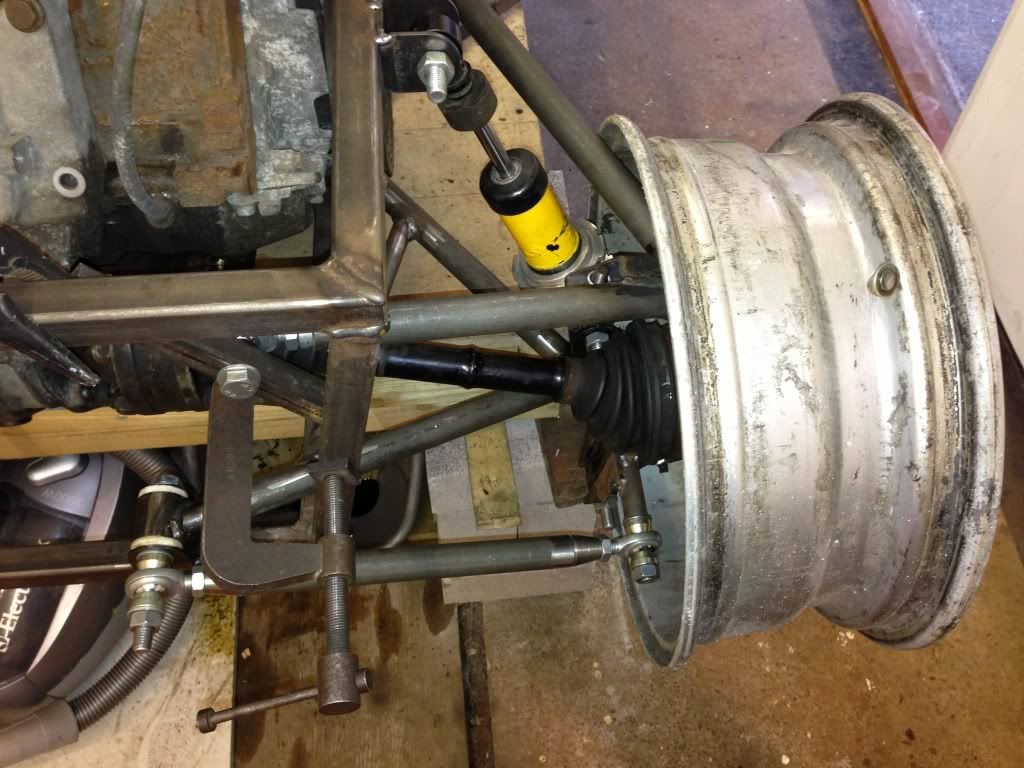
Last night I made up my brackets to hold the hub:
As a comparison, please see the Sylvia Mojo bottom arm, I based my design around that.
I am considering welding a tube onto the arm to replace the rose joint if people think that will improve the design. As I said, still got a few bits
to work on.
BT - I mentioned earlier about my pos neg camber mix up. I'm fully aware that during roll in a corner additional positive camber would give a
decrease in contact patch, not what I would want. Think that issue is sorted.
I also disagree that the toe control design is weak, I have seen many cars use similar. I would like to know exactly what it is you are concerned with
regarding it?? It isn't fully welded yet either!
I'm a big enough boy to be told I'm wrong, better to get it right now rather than later.
The triangle thing does bug me a bit, that steel plate on the end means that the arm is very unlikely to twist, so I don't really see it being an
issue, Marks is the same pretty much as the two rose joints fix to a flat out board end...
Thanks mark for your input, I like your set up and knowing it lasted 5 years of track abuse really helps me!
Rob
fregis - 2/2/13 at 02:53 PM
in my opinion too weak upper part, need connect both sides. But flip sides would maybe be better? get used toe rod out there where you belong
http://images54.fotki.com/v461/photos/1/1313721/11631039/null3-vi.jpg
[Edited on 2/2/13 by fregis]
adithorp - 2/2/13 at 07:17 PM
I'm no suspension design expert but...
That tube that the "toe bar" is attached to will bend on the first pot hole or curb.
I'd be surprised if it didn't bend just dumping the clutch.
[Edited on 2/2/13 by adithorp]
b14wrc - 2/2/13 at 07:47 PM
It has a stainless steel tube inside it by the way. Going to add a small plate across the tubes to add stiffness and have something to join the brake
pipes to.
Going to start again with the A Arms I've decided, will let you see my rethink as I go.
Rob
Doug68 - 3/2/13 at 02:36 AM
By way of reference here's some pictures of the Mojo rear suspension.
It's not how I'd choose to do it, but that's neither here nor there if its been proven to be sound in practice.


b14wrc - 3/2/13 at 11:16 AM
Thanks Doug,
Yes, I have seen that. Why would you not choose to do it that way? For me, using the fiat hubs was almost essential as my car is a midi.
Like I said, on the advice given I'm going to scrap the bottom A arm and redo to eliminate the use of a rose joint and make it a proper
triangle.
Rob
b14wrc - 11/2/13 at 07:56 PM
Hi Guys,
Not redone my A Arms yet, too much work on at the moment to get on with so not really been in the garage, however I did buy this:
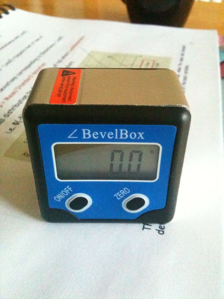
Nice little device, used it to rougthly check my current static camber settings.
The graph shows the NEGATIVE camber gain:
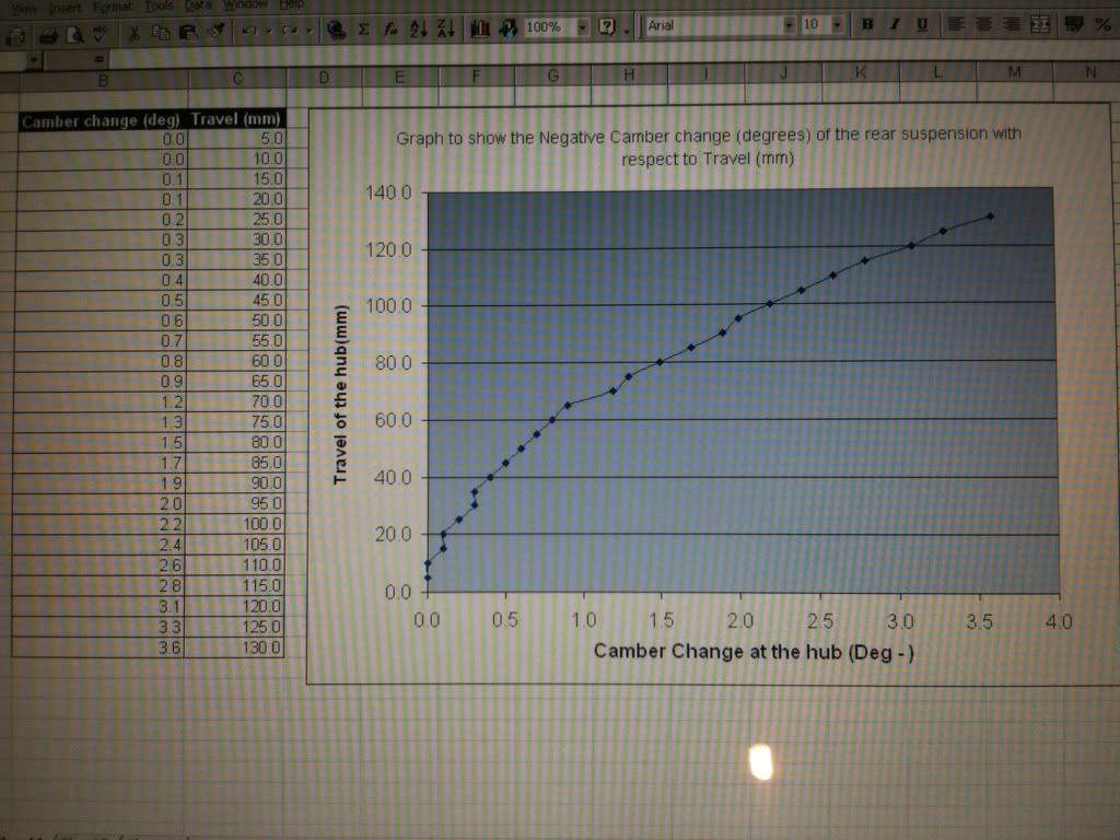
Question is, what do you all think of the amount of gain? Rembering that the bushes are not made yet and it's not all bolted up correctly,
it's a rough guild....
Also, just a pic of a lotus elise using toe control arms similar to my design.
Rob
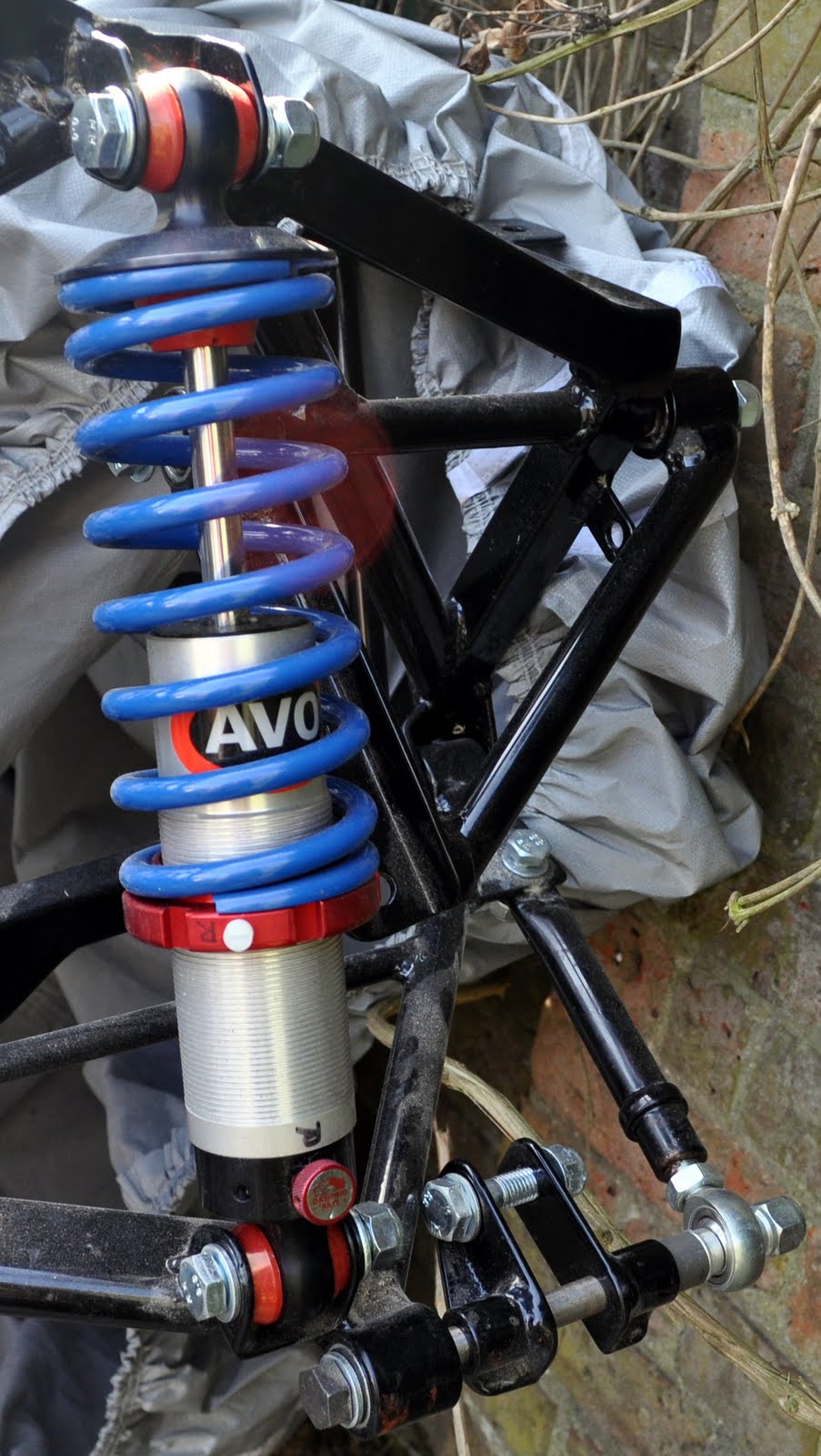
b14wrc - 23/2/13 at 02:39 PM
Hi all,
I am thinking about arranging my shock something like this:
Any comments??
Rob
RIE - 23/2/13 at 03:25 PM
quote:
Originally posted by b14wrc
Hi,
Thanks for most of the comments guys.
Last night I made up my brackets to hold the hub:
quote:
Originally posted by Doug68
First to say I'm not an engineer and I have zero welding skills, so this may be a daft question(s): your brackets seem to bolt to the upright
with no bar travelling through it, unlike the bolt in the Sylva setup - is that the case? If so, the welds are carrying the full force, right? Will
they be strong enough?
[Edited on 23/2/13 by RIE]
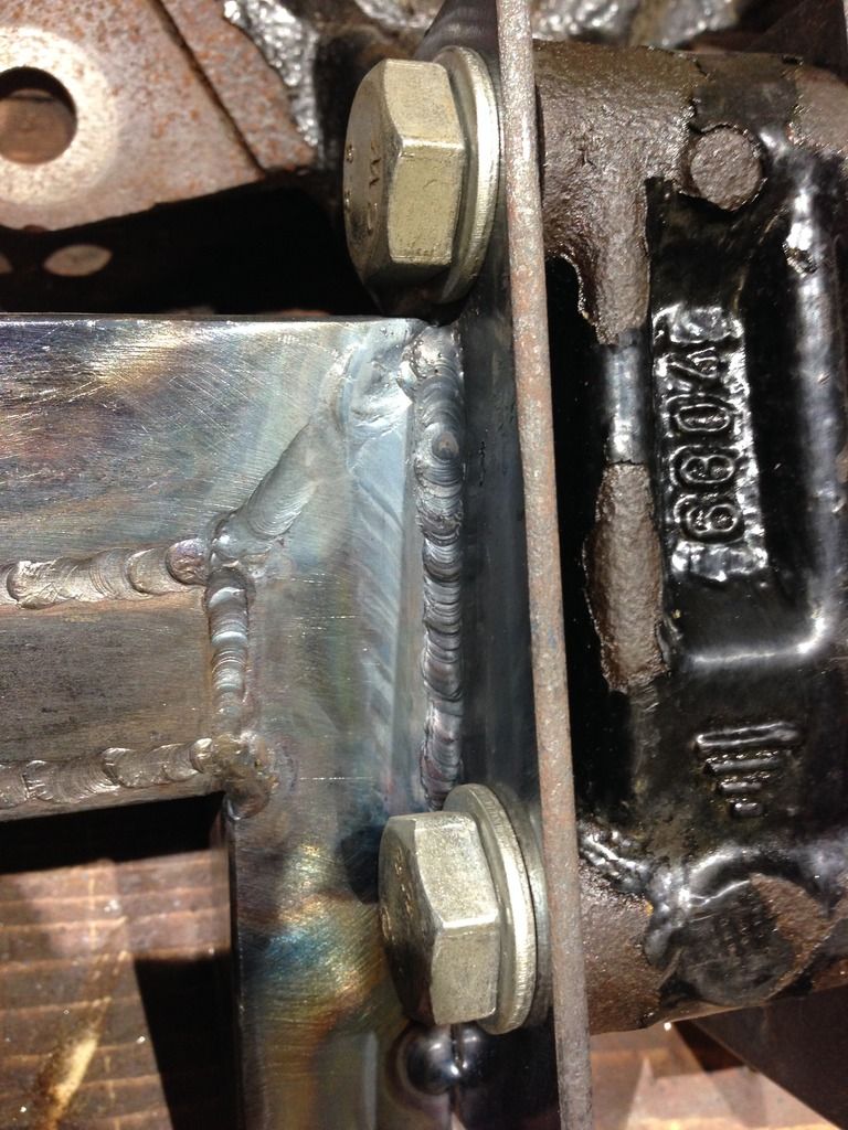
b14wrc - 23/2/13 at 04:09 PM
There is a 120mm long bolt going through the whole lot mate.
Plus inside that 20mm tube there is a ss sleeve. The load is not solely on those welds no.
Rob
phelpsa - 23/2/13 at 05:04 PM
quote:
Originally posted by b14wrc
Hi all,
I am thinking about arranging my shock something like this:
Any comments??
Rob
That looks like it will work to me Rob, certainly preferable to mounting it on the wishbone.
phil clegg - 1/3/13 at 10:29 PM
I like the fact you are building something slightly different.This sometimes means help is a bit harder to find and you become a develope engineer for
others.I prefer the non well travelled engine choice and wish you luck in the build...
b14wrc - 2/3/13 at 08:54 AM
Thanks Phil.
I havnt done much on the car as I have been busy with my MSc and work, but I have a week off at Easter and I'm hoping to get this rear suspension
finished completely.
I will update in a few weeks.
Rob
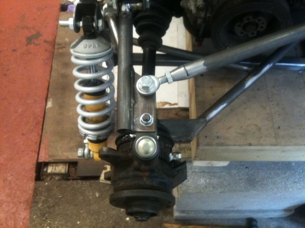
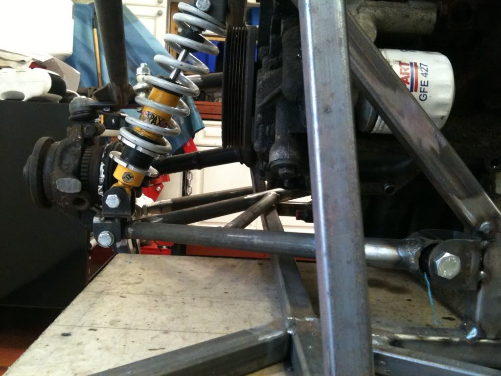
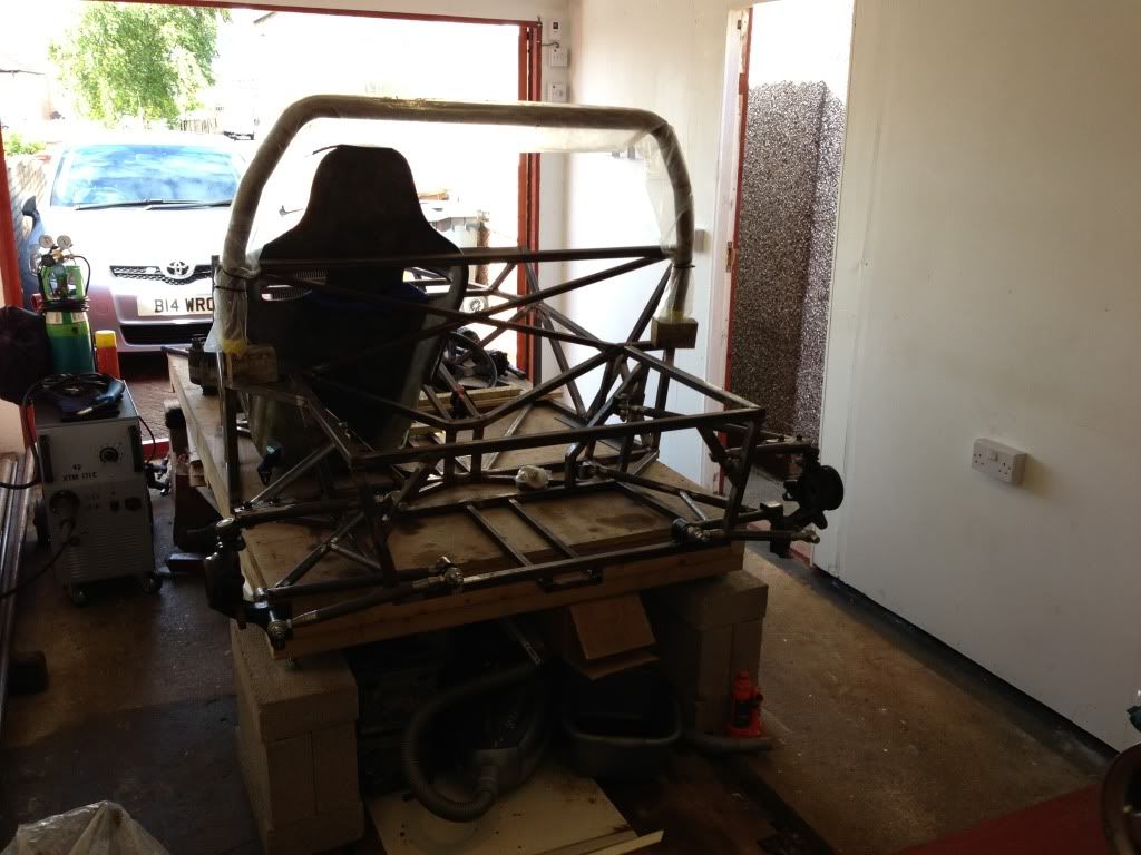
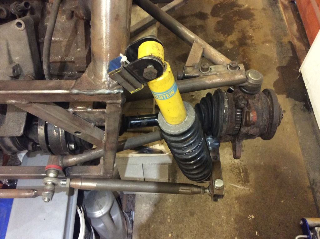
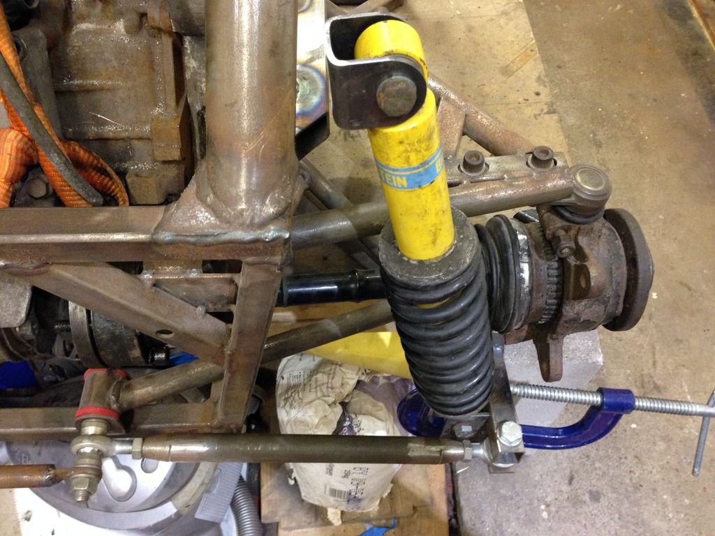
b14wrc - 4/4/13 at 12:01 PM
Hi all,
Well I had a bad day on Tuesday with the car, nothing seemed to work and progress was slow. Wednesday afternoon completely the opposite. Very pleased
with the final (not 100% welded and there are bushes to make!) design, it seems to work better than before and I now don't have the loading going
through that rose joint every one was concerned with.
The shock had to go infront of the drive shaft and you will see it isn't mounted directly to the bone. Also, the bottom arm is now a triangle as
suggested.
Any comments??
Rob
MikeRJ - 4/4/13 at 02:08 PM
Sorry if I'm being thick, but what stops the double 'U' bracket assembly from just flipping over? Is it welded to something on the
other side?
b14wrc - 4/4/13 at 03:15 PM
Do you mean the plate the ball joint bolts too??
If so, the trailing arm is a PU bush so won't slow the ball joint to flip over.... Is that what you mean? Good point though and I had thought it.
But should be ok....... I hope.
b14wrc - 4/4/13 at 03:16 PM
Lol. See what your saying now. That's welded to a peice which bolts to the up right, it can't move no.
britishtrident - 6/4/13 at 09:33 PM
Top arm is all wrong, a wishbone can be made up of two links but the second link has to connect so as two intersect at a point on the
imaginary line joining the ball joints on the first link, otherwise it is going to flop about if any compression force is put on the wishbone.
Using a bush at one end will make no difference.
mark chandler - 6/4/13 at 10:08 PM
Your wishbone mounting on the frame are not parallel with the centre line of the chassis, the top rear bracket to is closer to the centre line than
the front top, the bottom rears look to be an inverse of this so I suspect you will get rear wheel steering. It was far better the way you had it
earlier on in this thread.
I assume the top ball joint bracket extends to the second bolt, however as BT has stated you really want the ball joint to be the intersection of the
wishbones. Have you done it this way to ensure that when a wheel is fitted it does not foul the inner rim? If you have not dropped a wheel on this
assembly I suggest you do quickly as bones get in the way!
Although you have put a lot of effort into this I would suggest a redesign is called for before you go any further
[Edited on 6/4/13 by mark chandler]
[Edited on 6/4/13 by mark chandler]
b14wrc - 7/4/13 at 03:52 PM
Hi.
Yes the wheel clears the trailing arm and the bottom arms are spaced off the centre line exactly the same front/rear pick ups.
Once I have the bushes I will check the camber change through travel and see what steering changes might happen, to be honest I can't see how
that could happen as the bottom mounts are fixed in one plane of movement, ie the in and out, for rear steer I'd need toe alterations which from
my current trails "seems" ok.... May be wrong mind.
BT, I know what your on about with the 'flop' I will also check as was a concern, I may end up welding the camber control arm directly to
that ball joint plate. Will see how it all works once bolted and bushed.
Regards, Rob
PS, yes, a lot of effort so far has gone into this.
 possibly an understatement!
b14wrc - 20/4/13 at 04:14 PM
I've made some temporary bushes now to get the suspension working, so far, seems good.
These bushes are too hard and brittle, going to have a better mould machined at work and cast some PU rubber ones.
Top arm is still being thought about with comments made earlier. I'm thinking simplifying it to a single A arm mounted with two rose joints.
Rob
b14wrc - 3/6/13 at 10:17 PM
It's been a while chaps, finally got in the garage on Saturday!
Does this look a better design?
Still a bit to do, but it's coming along....
Rob
the1theycallthe1 - 4/6/13 at 01:39 PM
Looks great.
b14wrc - 27/7/13 at 07:55 PM
Hi all,
Had a bit on recently and only got back to locost last week. So, I wasn't happy with the mk 2 upper rear arm, basically it didn't work.
Camber control was difficult to adjust and the front pick up is not aligned with rear, so that needs changing.
I have made this for adjusting my camber:
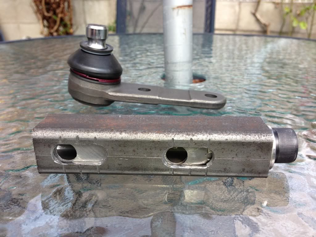
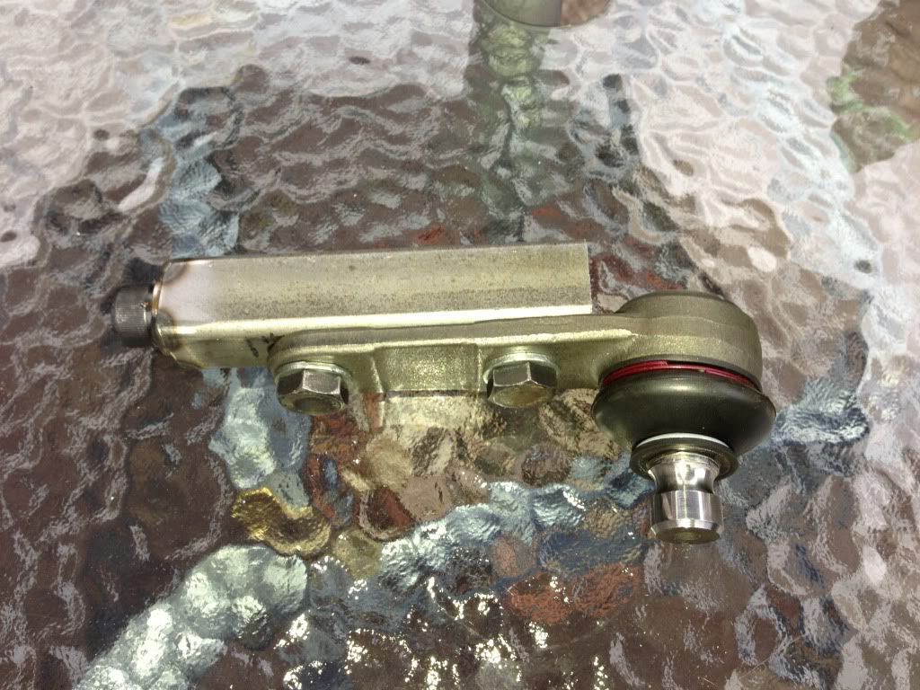
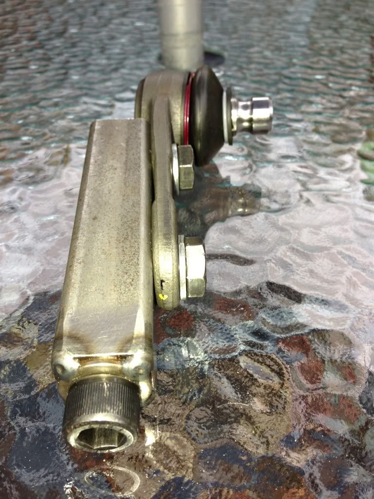
So now I need to make a new arm based around this, by turning the screw the ball joint is adjust in and out, then you just lock up the two bolts, took
a bit of making but seems to work very well.
Rob
[Edited on 27/7/13 by b14wrc]
b14wrc - 28/7/13 at 10:37 AM
Uphill Racer - 28/7/13 at 10:37 PM
Are you sure your figures on negative camber are right?
I know pics can give a false view but from them it looks like the arcs send the upright into positive camber.
b14wrc - 29/7/13 at 11:39 AM
Hi uphill racer,
Thanks for your comments. Are you looking at the graph results? Wondering where your thoughts for the camber issue came from. That graph refers to the
old set up � I haven�t yet tested the new arrangement to the same accuracy and graphed the results. However I have done a quick check on the current
set up with my angle gauge and it defiantly does increase in negative camber as the suspension moves through its range. Exactly how much the next
generation arm will give I am not yet sure, but before I was getting about 1.5deg of travel for about 2� of travel, this is similar to an Elise I
think I read so should be in the right ball park.
The new design should mean I can dial in the static camber very easily. The only issue I have at the moment is that the front pick up is too far out
board and the engine is going to have to move back for the mount to move inboard, this is doable though and plan to get the engine out this week and
get it completed by the weekend.
One other major change is the shock is going to have to move, probably mount on the arm rather than the hub as it is at the moment�
Regards, Rob
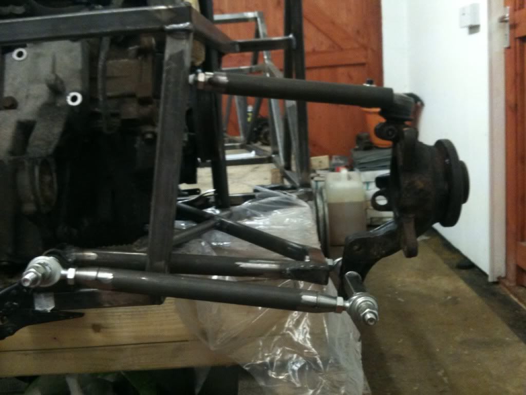
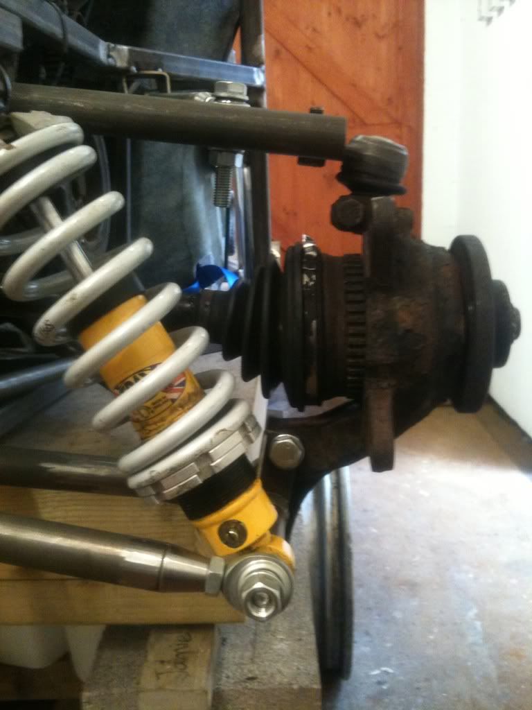
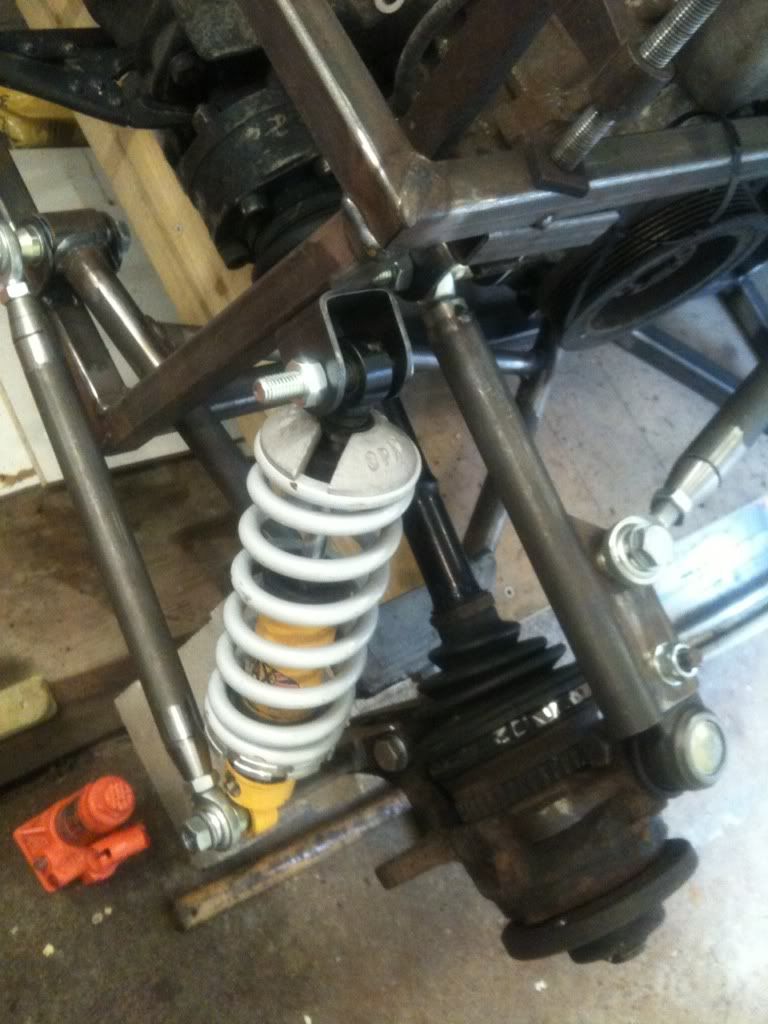
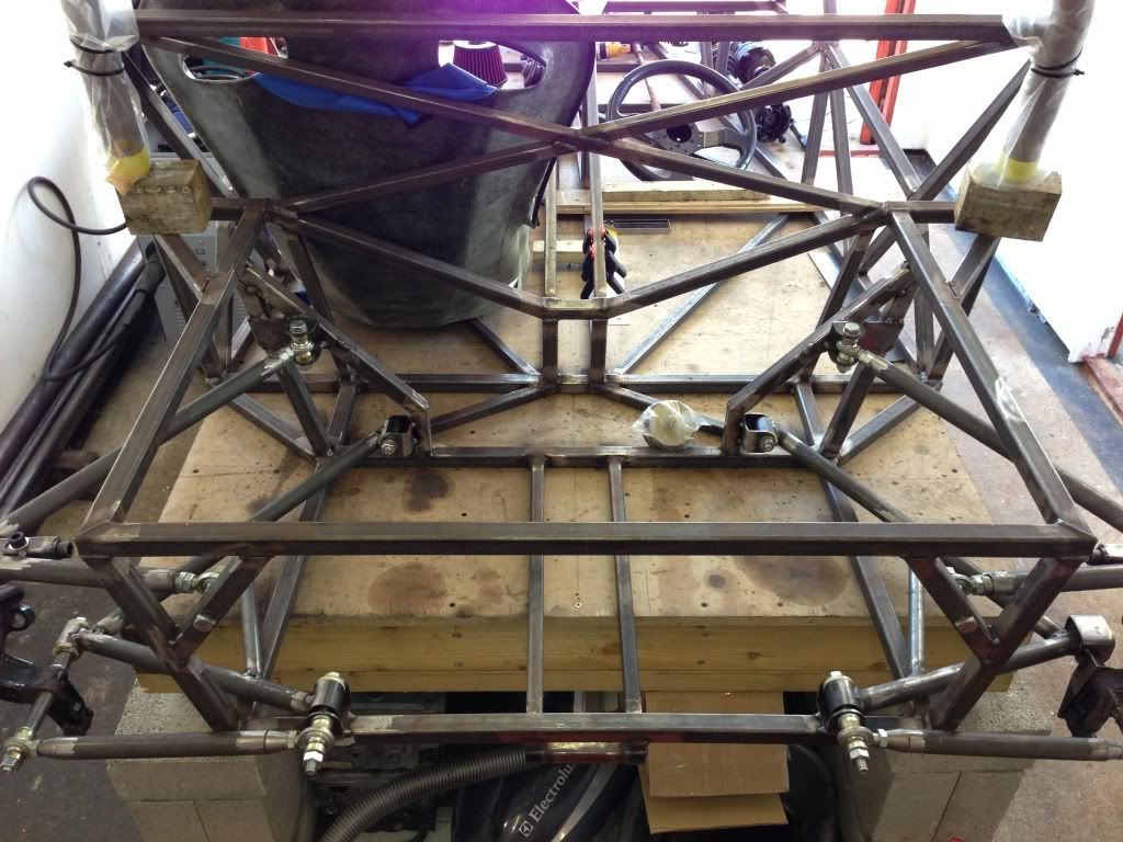
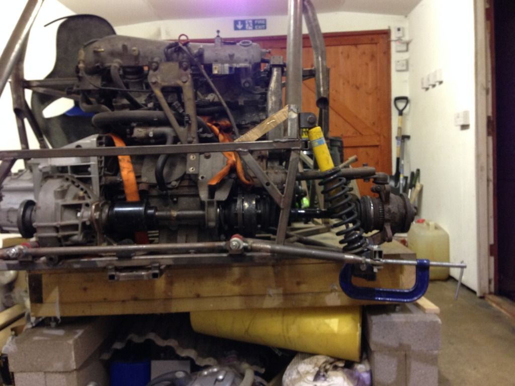
b14wrc - 3/8/13 at 01:02 PM
This is a better photo of the suspension angles. Not sure exactly what the ride height is going to be, I guess between 140-120mm, which means the
bottom arms will be level or slightly pointing down at rest.
Once I have made the final top arm incorporating my new camber adjusters, I can recalculate the camber gain, but from the position of the upper mount
points, I am expecting similar to before.
I've also fitted better front mounts for the top arms, once all welded, I think it will be pretty rugged.
Rob
b14wrc - 10/8/13 at 07:57 AM
Hi,
Just a quickie:
Rob
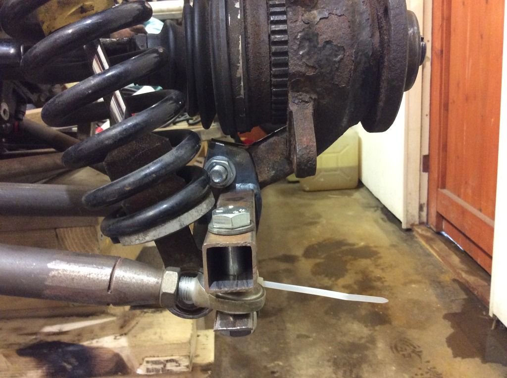
b14wrc - 10/8/13 at 07:34 PM
b14wrc - 11/8/13 at 07:01 PM
[Edited on 11/8/13 by b14wrc]
Volvorsport - 11/8/13 at 07:20 PM
are you running those hubs upside down for a reason ?
b14wrc - 11/8/13 at 07:26 PM
Yes, I wanted the ball joint at the top and not the bottom.
Issue??
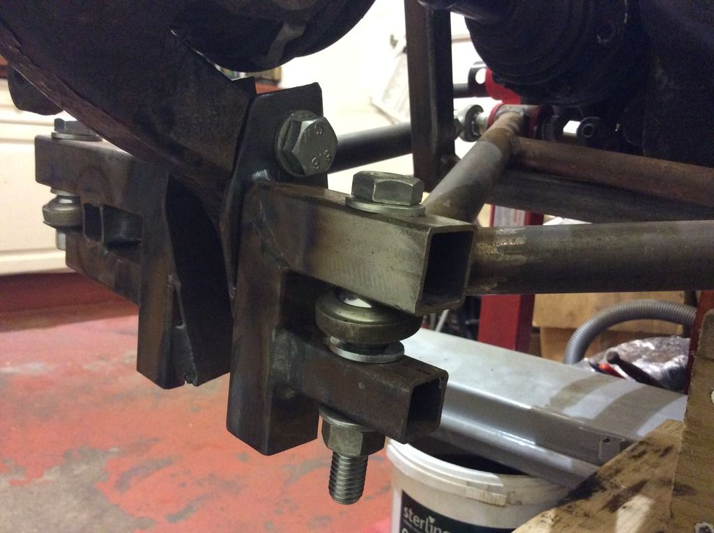
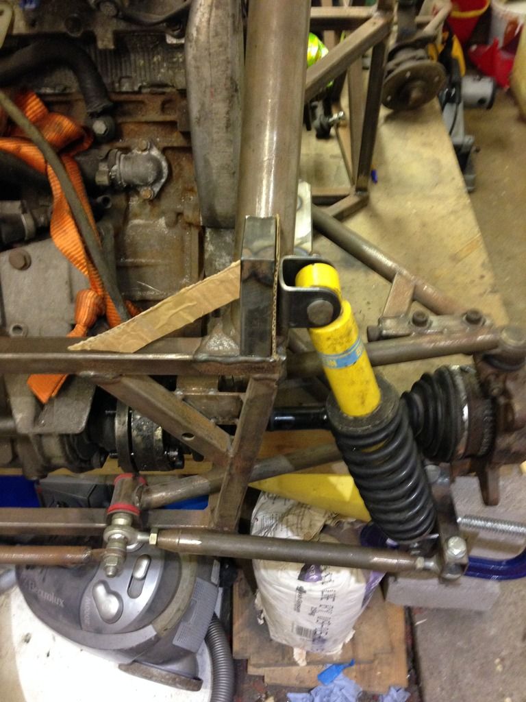
b14wrc - 4/2/14 at 10:18 PM
b14wrc - 4/2/14 at 10:23 PM
Hi all,
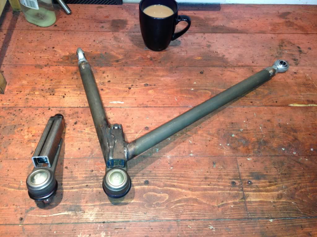
Managed to find a little time to work on the car last weekend. Upper rear arm now finally in place, I've welded a bracket onto the rear pick up
point so the rose joint sits in the correct plane of rotation.
And the square section joining the front rod on the wishbone is where the shock will mount. It's a neat solution I think....
Rob
nick205 - 5/2/14 at 12:43 AM
Hi Rob
Looking at the design I really think the rear upright will be prone to twisting under load. It just doesn't look right to me with the long bolt
as the pivot arrangement.
Would you not be less constrained if you fabricated your own uprights along the lines of how MK and others do it?
Meant constructively BTW
ashg - 5/2/14 at 02:07 AM
sorry someone has got to say it that rear suspension setup is abysmal. the bottom long bolt is going to bend/twist from the engine torque. the inner
rear bolt is for the rear part of the lower arm is unsupported on one end so that will bend too.
pleas don't take my comments in a negative way i really don't want you to get hurt, what you have done is dangerous!
try doing it this way the fiat inner cv joint will most likely be 100mm or 108mm. remove the outer cv joint and put a inner joint on the outer part
of the driveshaft. that will give you a driveshaft end that should mate up to a sierra rear carrier/drive spline ( they come in 100 and 108mm) then
you can use a more conventional rear carrier like you see on most irs 7's and many other sports cars.
again sorry to throw a spanner in the works but the upright your trying to make use of is completely unsuitable. the only way the mojo is getting
away with such a poor design is the fact that the span of the lower bolt isn't so wide and it will make less than half the power of that coupe
5pot.
b14wrc - 5/2/14 at 07:18 AM
Blunt!
Just so you know, the long bolt is being changed, I've started making the parts, it's going to be quite different, so if that's the
only area of concern I'm not that bothered. Also the two lower brackets are going to have some extra tubes joining to them, these will integrate
into the engine/gearbox mounts.
Looked at using ford uprights, the drive shafts don't match, so it's a non-starter.
b14wrc - 20/2/16 at 03:47 PM
Hi All,
So it's been a long time since this thread started but I have had loads on and only got around to progressing a bit more on this. I need some
help and advice around mounting my shock, below are some photos to show progress. It's still not completely welded and it is still mock up, but
this is about the 5-6 rear suspension design and from an engineering point of view I am now pretty happy with it. It will have some additional steel
work added to link the two halves of the lower hub bracket and the wishbones are getting some extra steel. As said, my concerns are over position of
the shock, I'm thinking one of the mounts needs to be a rose joint if I go this way as when adjusting the track with both ends of the shock being
bushed I'll run into twisting issues?
I'd prefer it low down rather than mounting it to the top arm, can't mount to the bottom arm as the gearbox is in the way on the other side!
Lol
 [/UR]
[/UR]
[URL=http://s1126.photobucket.com/user/b14wrc/media/EAE364B8-3508-4A86-822F-74AA3DE2D647.jpg.html]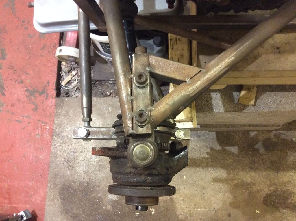
Let me know what your thoughts are. I've also got the rear brakes almost sorted....
Rob
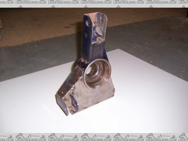
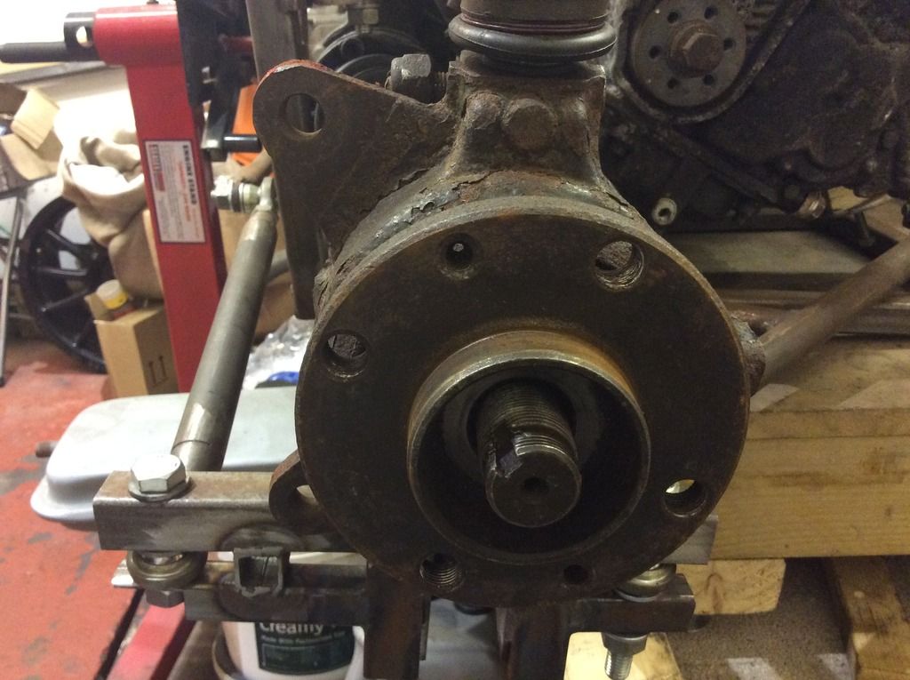
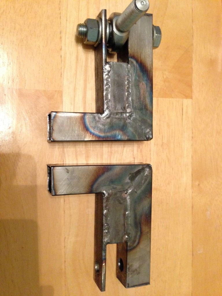
b14wrc - 23/11/16 at 10:24 PM
New bottom brackets/hub carriers.....
Weekend I'll be making a full new set same as these prototypes. Need to adjust hole positions slightly and make them easier to weld, getting the
TIG in was tricky, got some good ideas. Once these are finished, I'll mount the shocks to them and the chassis, completing the rear suspension at
last!
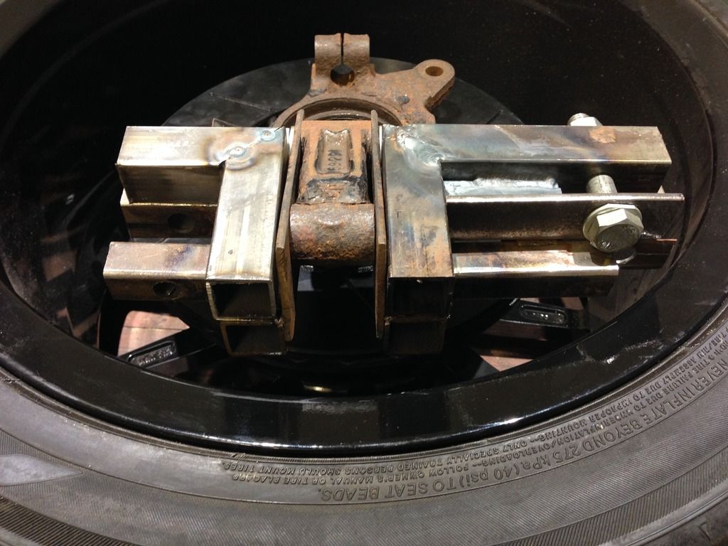
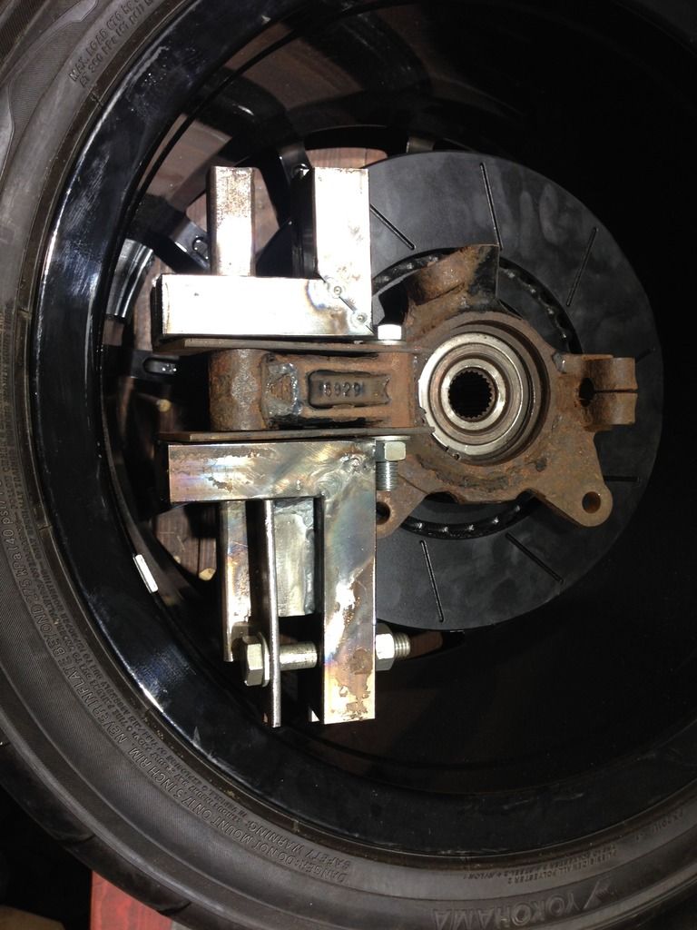
The photos show the old parts over laid to the old design, main issue was the closeness to the rim and the mods meant a nasty stress concentration at
the corner next to the bolt, basically rubbish so I've had to redo (several times).
Nickp - 24/11/16 at 07:43 AM
quote:
Originally posted by b14wrc
Yes, I wanted the ball joint at the top and not the bottom.
Any particular reason?
b14wrc - 24/11/16 at 12:35 PM
Hey,
Well for starters I am obviously not following the crowd with my engine choice. This kind of forced me to use the front wheel drive hubs, people
suggested ford but the drive shaft splines wouldn�t align and to be honest I didn�t want to get into hybrid drive shafts, I have made enough custom
bits so far and wanted fiat running gear straight through to ensure spares are easy to attain.
The reason for the ball joint at the top, well it could have gone at the bottom, but then you would need to mount some sort of arrangement to fit a
ball joint to the mcpearson strut holder (messy) or fit an arrangement to fit two wishbones to that part similar to what I have tried at the bottom. I
cut the steering arms off because A I didn�t want bump steer issues, which I think I would have had as mounting points were limited, and B this way,
my heavy bits are lower down, in fact I reckon the solution is now pretty optimised, I get a comparable dynamic suspension travel to an Elise
(Actually Measured) and manage to package everything in around the 5 Cylinder nicely and still allow access for adjustment. Lotus run ball joints on
the top and bottom, which is king of what I�m now going for with the rose joints.
The rose joints will eventually be booted � inboard joints are PU. On my S1 Elise I had rose jointed toe links � very similar set up to what I will
eventually have here, so don�t see an issue.

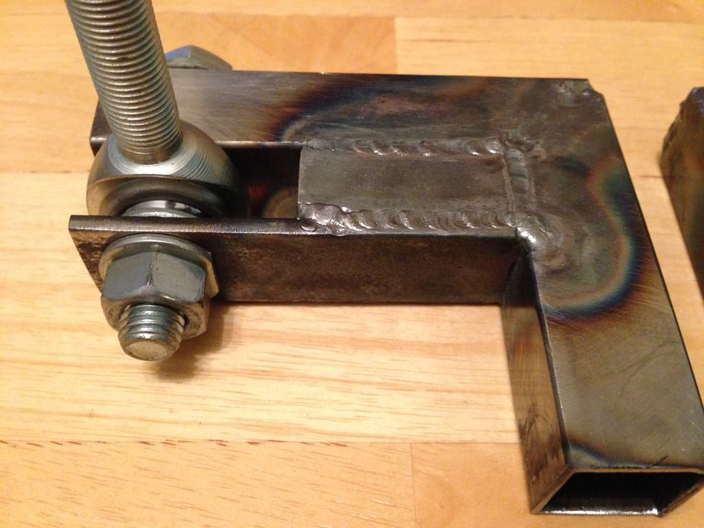
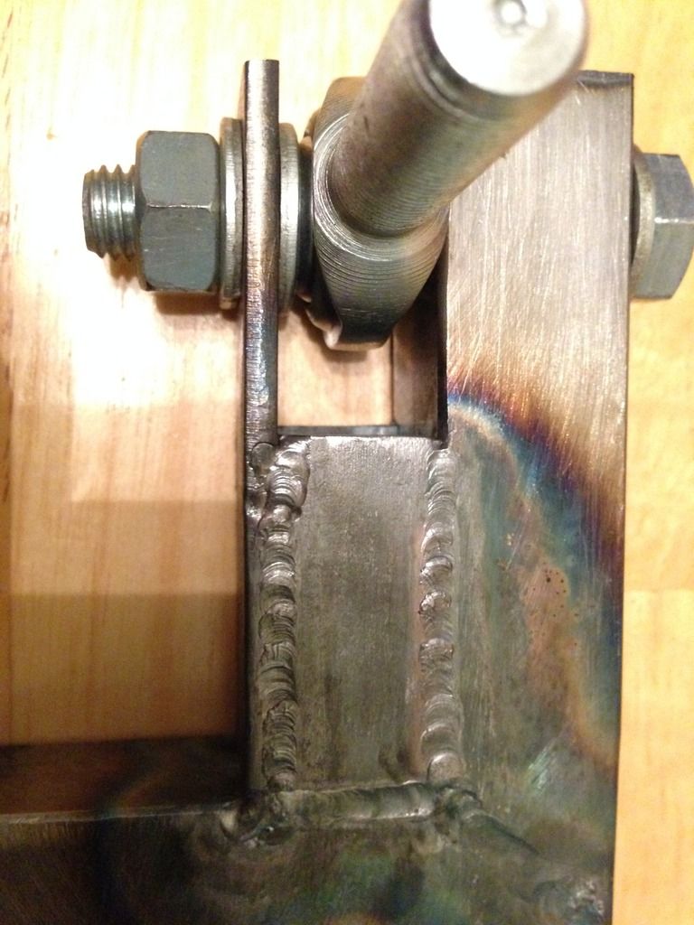
b14wrc - 25/11/16 at 08:53 PM
Pretty pleased with next stage on the hub carriers.
Rob
b14wrc - 26/11/16 at 01:03 PM
Installed the (not finished) new rear hub carrier. I will be making a new forward part then two brackets that will weld the two parts together.
Lengthening the forward part should also provide a slightly better angle for the rear toe arms. Once finished I will weld my shock mounts to the rear
section, going to rose joint that connection so there is ajustment when the toe is changed, if that makes sense...
Rob
b14wrc - 26/11/16 at 06:04 PM
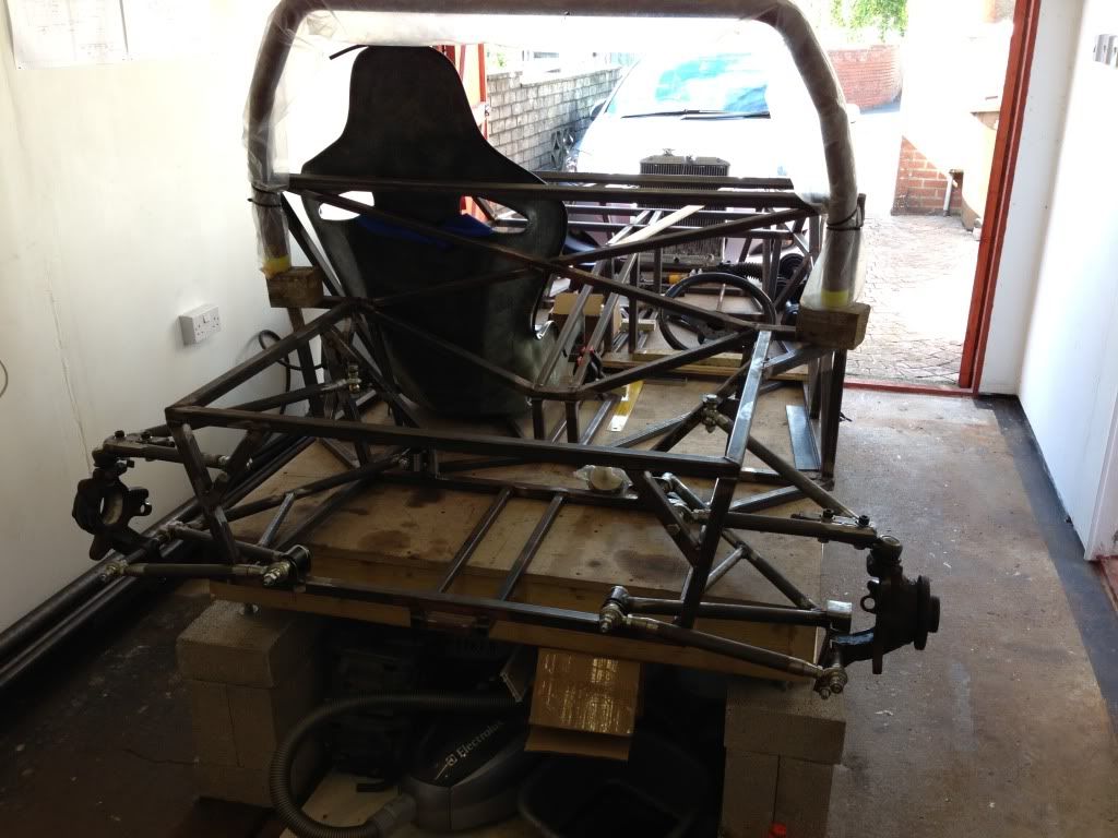
b14wrc - 4/12/16 at 11:43 AM
Hi all,
Sunday morning update....
Completed the final rear suspension set up, both sides.
I still have to join the two sections and add brackets for the shock to mount.
Rob
Matt21 - 5/12/16 at 10:53 AM
Am I seeing this correctly...
The uprights you are using at front ones from a fwd car?
And the way you have them held with the suspension arms means that the only thing holding them straight is the rear part of the upright with the 2
bolts through it?
Surely that isn't very strong? and a hard corner or braking would try to turn the rear wheels and potentially sheer that part off, meaning you
suddenly get an uncontrolable rear wheel steer car?
I think I would be looking at making the top mount where the ball joint is into a solid mount too, or better yet, use some uprights with the track rod
end arms still on and make an adjustable link to the chassis which would be stronger and also allow rear toe to be adjusted?
But maybe I have completely the wrong idea!
Also, how come you went with those uprights and not for the usual rear uprights that are bolted through at the top and bottom like these?
b14wrc - 14/1/17 at 11:30 AM
Started making the bottom shock mounts.
Just need to figure how to make a good strong top mount, I'm thinking of making a cut out in the bottom chassis rail so the arms can go slightly
lower, the shocks are S2 Elise and have about 65mm of travel to the bump stops. I haven't tried the suspension with the motor in yet obviously so
it's all a bit trial and error.
Also, I am going to chop the bushed joint off the bottom of the shock and change for a rose joint, or eventually buy new shocks, I will have issues I
think adjusting the toe as it is at the moment as the spring will tend to resist the twisting movement.
I couldn't mount the shock directly to the bottom arm.
Rob
b14wrc - 20/1/17 at 08:34 PM
b14wrc - 18/2/17 at 11:02 AM
Mocked up the new shock bottom mounts this morning. Happy with position now.
b14wrc - 27/2/17 at 12:35 PM
quote:
Originally posted by Matt21
Am I seeing this correctly...
The uprights you are using at front ones from a fwd car?
And the way you have them held with the suspension arms means that the only thing holding them straight is the rear part of the upright with the 2
bolts through it?
Surely that isn't very strong? and a hard corner or braking would try to turn the rear wheels and potentially sheer that part off, meaning you
suddenly get an uncontrolable rear wheel steer car?
I think I would be looking at making the top mount where the ball joint is into a solid mount too, or better yet, use some uprights with the track rod
end arms still on and make an adjustable link to the chassis which would be stronger and also allow rear toe to be adjusted?
But maybe I have completely the wrong idea!
Also, how come you went with those uprights and not for the usual rear uprights that are bolted through at the top and bottom like these?
Hi Matt,
My rear suspension does have adjustment for toe, its really easy, just wind in or out the toe link at the rear, same as the Lotus Elise. Saw your post
about your toe adjustment, and note the design of your car does not have adjustability for toe, hence why I didn't go for a similar arrangement.
I wouldn't want to have to shim it to change the toe, I am planning to use shims on the front upper arms to change caster. So from that point, I
am kind of limited on packaging space. I did consider mounting my shock off the top wish bone, but it would mean the CoG is higher and make adjustment
more difficult with the car sat on the ground. Plus I want my body work to be as tidy as possible, meaning no additional items to make the rear clam
longer or wider and the wheel arches should still look 7 style.
I have tried building my car as accurately as possible, but I'm sure there will be error (+/-5.0mm) and hence why camber and toe are adjustable.
Yes, front wheel drive hubs from my donor, I wanted to use these as it make my driveshaft choice and install easier, ie standard coupe 20vt ones.
People have commented on this before and I can't really see why its a problem.
Regarding the steering arm, I removed these to eliminate bump steer, I would have had problems with mounting them in a position which would have
introduced unwanted rear wheel steering. I feel my method is simpler.
Ford hubs wouldn't fit with the fiat drive shafts.
Rob

 [/UR]
[/UR] 


