
Aluminum scuttle (again)
C10CoryM - 28/12/09 at 05:45 AM
Hey guys,
Some time ago I asked about making an aluminum scuttle and got some good help. Now it's time to actually design and build the thing and I
would like some more  .
.
Firstly, I need to make a flange in the front of the scuttle so that the hood will sit on it, and be flush. What is the best way of doing this? I
was playing around with a flange tool used for lapping panels and it seemed to work well even on the curves. Only thing is it only gives about a
1/2" flange and it's not very deep.
I have access to a big english wheel (which I could buy some roller bearings for and make a "joggling tool out of), a tig welder, a shrinking
tool and a stretching tool. Thing is I have never used any of those tools 
Will I be able to flange the front before/after bending the curve? Or am I better off learning how to TIG weld and just welding a flange on? Or is
it time I get the resin and kevlar/carbon fibre out and make the scuttle of that?
I have some other questions I would like some input on, but I will take some pictures tommorow to explain what I mean. Cant decide the best way to do
my panelling under/to the scuttle.
Thanks for any help.
Cory
907 - 28/12/09 at 10:56 AM
Hi.
I can think of three ways to make a scuttle.
1. Develop, or copy from another car, the shape on paper and cut the ally to the paper template.
2. Make a metal frame to knock the ally over that may or may not become part of the structure.
Form ally over frame and cut ally to suit.
3. Make dash and bulkhead plywood formers and screw to cross members to make a frame to knock the ally over.
Cut ally to suit as you go.
The dash former could even be used as the dash if covered with foam and vinyl.
I don't like the idea of welding due to distortion otherwise this would be number 4.
I wanted my scuttle to be removable so I did number 2. My column has a joint and all the wiring has multi pin plugs.
The only other connections are water heater, oil pressure pipe and speedo cable.
The whole thing lifts off, steering wheel and all.
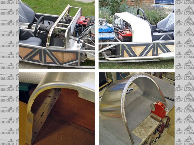
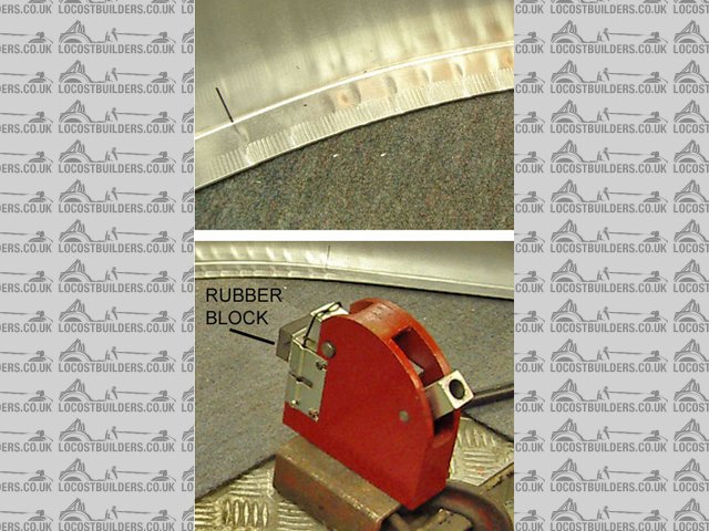
I did have a problem on the top corners, (125 rad) as 25mm is too much to knock over so I cut a bit out
with an air nibbler to reduce the flange width. (see pic)
I used a length of ally angle for the bonnet seal support and stuck 6mm foam rubber on it.
This covers the rough nibbled corners up.
I now have a shrinker which I bought to make my rear arches (see pic) so if I were to make another
I would use that on the scuttle corners.
If I can be of any more help feel free to ask.
Cheers
Paul G
[Edited on 28/12/09 by 907]
Rescued attachment scuttle pm.jpg
trextr7monkey - 28/12/09 at 12:24 PM
Good to see some high quality sheet metal work, well impressed!
atb
Mike
907 - 28/12/09 at 02:16 PM
Thanks Mike.
I too was impressed with the way it turned out; but then again, I'm very easily impressed.
Cheers
Paul G
RK - 28/12/09 at 02:26 PM
Paul, you're a barsteward. That looks too good to be on this forum! VERY nice!
C10CoryM - 29/12/09 at 02:21 AM
Thanks Paul.
I think I will just use the shrinker and make an aluminum scuttle with no frame for now. I am going to run this summer (hopefully) without a
windshield etc. The only thing the scuttle will support now is itself, a wind deflector and some mirrors. When I add a windshield and wipers I may
have to make a new one.
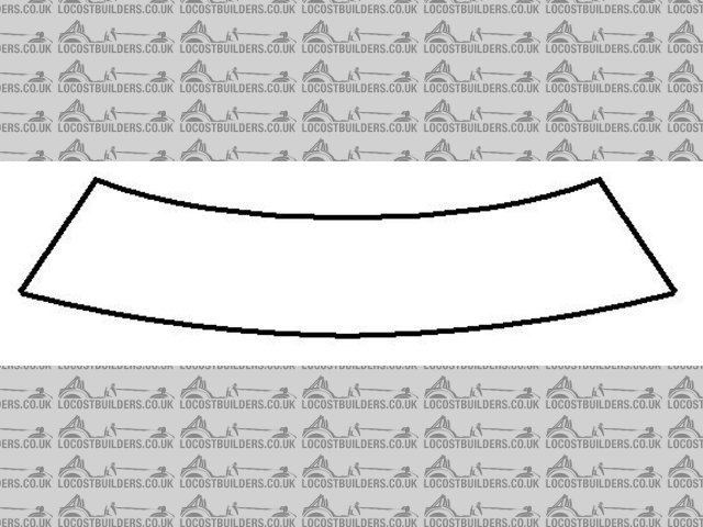
I was hoping to have a flange like the one attached for the hood to sit on, but I doubt I would be able to bend the scuttle with it. I think I will
use the shrinker and make front and rear like the rear of yours, and rivet on a flange to support the hood.
I think I figured out the panelling for now too. Going to try to pick some aluminum up tommorow and play. What thickness/type would you recommend?
Do you anneal?
Cheers.
Cory

Rescued attachment joggle.jpg
Ivan - 29/12/09 at 07:06 AM
I've been thinking about my scuttle as well - what I thought of doing was to make the scuttle & bonnet in one piece as my nose cone
isn't flat on top and to get matching curves is difficult with the risk of bulging and denting.
Once all bent up would cut off scuttle and rivit or sloder to flat to create the indent for the bonnet.
Would end up with perfectly aligned bonnet, nose cone and scuttle from all views.
C10CoryM - 29/12/09 at 07:42 AM
Not a bad idea really Ivan. It would give you a good line between the scuttle and bonnet. Just rivet or weld a flange on the scuttle to support the
hood after. Also have to make the bulkhead attach to the scuttle top somehow.
Not really an option in my case because my bonnet is going to be a bit difficult due to the large lump sticking through it. Also Im not sure I like
the look of a sharp bonnet edge against a sharp scuttle edge.
Im just going to get the scuttle and bonnet done and expect to be re-doing it eventually
Mark Allanson - 29/12/09 at 10:08 AM
This is how I did mine
907 - 29/12/09 at 12:06 PM
Hi All,
Bearing in mind Ivan's post, I ran a string line down the centre of the car that just cleared the engine.
By laying a straight edge across the top chassis rails I measured up to the string at various points.
This gave me the height and slope angle of the scuttle, front and back, and the height of the nose,
and ensured that when the bonnet was fitted in between it would be one line from top edge of the
dash to where the nose drops away.
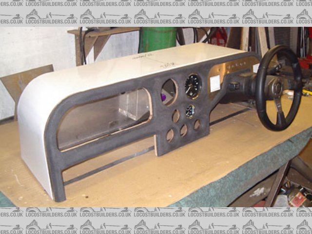
Cory, I think you are right to dispense with the frame. Mine is there just to support the column. (see pic)
Having worked out the slope angle / bonnet line I sloped the dash forward at the same angle to give 90deg
between the two. This seemed an easy way to do it as the scuttle sheet edge is then a straight line and I
could work from the edge of the sheet of ally. One edge less to cut.
With the scuttle top & sides formed and a lip knocked over all round this would hold shape.
With a dash on one side and bulk head the other I think it would be quite solid.
An angle could be added when riveting the bulk head, the rivets holding all three thicknesses.
(I'll do a drawing to explain it better)
Cheers
Paul G
Rescued attachment scuttle dash.jpg
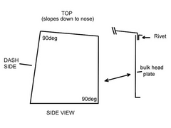
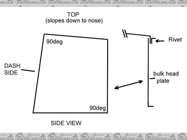
907 - 29/12/09 at 12:12 PM
On reflection I should have mounted the column on the chassis as Mark has done.
Anyway, (rough) drawing below.
Cheers
Paul G
Rescued attachment scuttle drw.jpg
C10CoryM - 29/12/09 at 09:20 PM
Thanks guys.
Paul, that is pretty much what I have in mind. When I install a windsheild and wipers I will add some framework to support those.
One more question for now: My shrinker/stretcher jaws are only about 1" deep. Does that mean I should bend a 1" flange then shrink to get
my scuttle curve? Will I get ripples on the visible part if I go over 1"? I will be painting so a little filler is fine.
Cheers.
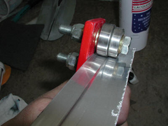
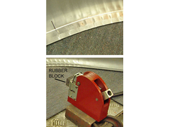
907 - 29/12/09 at 11:30 PM
Hi again.
If you were to bend a 1" flange then it is the edge that needs to shrink the most, so you only need the jaws to cover say 1/2".
I stuck a piece of the rubber that I used to pad the dash on the front of the shrinker to act as a spacer. (see pic)
This process will put "tuck" marks in the rest of the flange but these can be dressed out with a flat faced hammer and a heavy block on the
other side.
You may need to shrink, then dress the tucks, then shrink more, etc.
Any remaining marks on the outside of the flange can be taken out with wet & dry. No need for filler.
The inside will not be seen and most of the outside will be covered by the angle & rubber bonnet strip.
Practice on a piece of scrap first.
I hope this is of help.
Cheers
Paul G
Edit to add: material was 1.5mm (16g) half hard ally.
[Edited on 29/12/09 by 907]
Rescued attachment shrinking.jpg
907 - 30/12/09 at 12:08 AM
Since I've not posted a pic of the car for ages, see below.
I'm just a bit proud of it. (smug grin)
Paul G
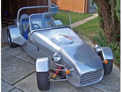
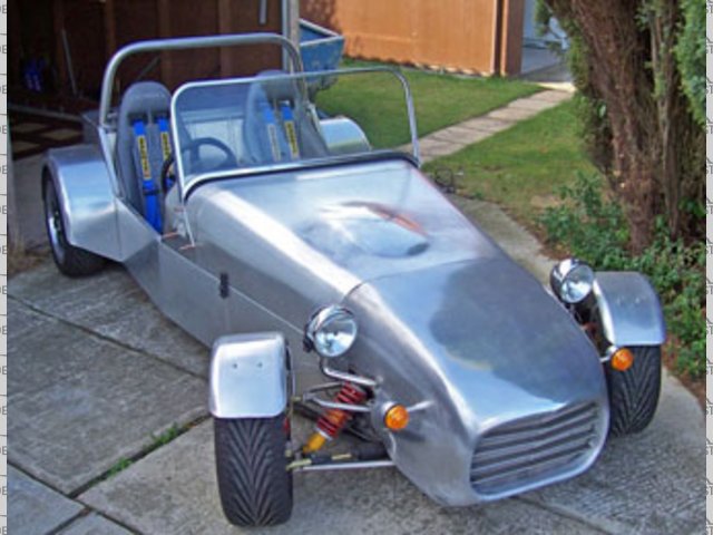
Rescued attachment suttol ws s.jpg
C10CoryM - 30/12/09 at 04:14 AM
Definitely helping Paul. Thanks. I got my front bulkhead and my dash to shape today. I do plan on making a carbon dash, but the aluminum will do
for now. Will have to wait until the weekend to play anymore.
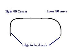
Since you are being so helpful I will ask another question. Refer to the attached drawing. Say that is a cross section of a rear fender, how do
you go about getting the nice radius curve w/o ending up with flat spots? If the bend is a tight 90, you should be able to just shrink it and nothing
more correct?
Thanks again Paul. Alway nice to have someone helping me for a change 
You car looks good. Didnt I remember some pictures of a hard top? How did that end?
Ivan, I realized one problem with your idea while measuring. The top piece of the scuttle will be over 4ft wide. Meaning its going to be hard to
find a sheet of aluminum the size you need.
Cheers.
Rescued attachment aaa.jpg
907 - 30/12/09 at 08:11 AM
Hi Cory,
Trev D is making a hard top for his 7. Now there's a true craftsman.
Epona is the car designed by my son (Gaz1977) and is on hold at the moment.
I think everyone is awaiting better times before spending money. 
The shrinking machines used by professionals (like Trev) have a deep throat and allow you to shrink well into the sheet.
They are powered and the dies nip the sheet many times a minute.
For us Locosters another plan is needed.
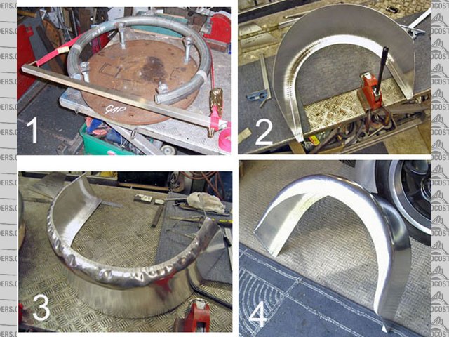
I made a jig from a rolled length of pipe. It's down to what you have, so others might use wood and shape it with a sander. pic 1.
Pic 2 shows the flat sheet, 90deg fold, then pulled to shape with just the shrinker.
Pic 3 (yup, frightening isn't it?  ) shows the next stage.
Clamp in the jig with the luggage strap and dress over with a rubber mallet.
Out of the jig and shrink the edge. Back in and dress. Shrink, hammer, shrink, hammer, till a rough shape is achieved.
Into the E wheel and take out the tucks, wheeling from the shrunk edge to the flat centre area and back, working round the fender.
Don't wheel into the area you want to stay flat.
(My first two ended up in the scrap bin. )
I then cut off the chewed edge the jaws had made and welded in a crescent shaped piece, wired the edges and we have pic 4.
I find shaping ally very time consuming but very satisfying. A sense of achievement and all that.
Good luck (and post pics)
Cheers
Paul G
Rescued attachment rear arch pm.jpg
NS Dev - 30/12/09 at 03:32 PM
very nice work there!
C10CoryM - 2/1/10 at 12:26 AM
quote:
Originally posted by 907
Having worked out the slope angle / bonnet line I sloped the dash forward at the same angle to give 90deg
between the two. This seemed an easy way to do it as the scuttle sheet edge is then a straight line and I
could work from the edge of the sheet of ally. One edge less to cut.
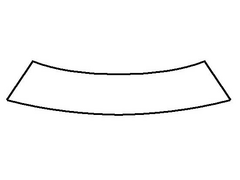
Im a little confused regarding this. Because the front bulkhead is narrower than the rear bulkhead wouldnt you end up with a curved line? If you had
a straight line and attached it to the dash, then tried to attach it to the smaller bulkhead, wouldnt you end up with a C shaped piece? Like attached
picture. A straight line would be nice as it would let me just bend a flange and shrink it right? Then form the bulkhead over a wood former.
When forming a curved piece like that you bend it over until it starts to buckle, then just shrink beside the buckle until it goes away? Then run
over where the buckle was with the shrinker and back to the former and bend it some more and repeat?
Thanks again.
Cory
Rescued attachment cutt.JPG
907 - 2/1/10 at 10:09 AM
quote:
Originally posted by C10CoryM
quote:
Originally posted by 907
Having worked out the slope angle / bonnet line I sloped the dash forward at the same angle to give 90deg
between the two. This seemed an easy way to do it as the scuttle sheet edge is then a straight line and I
could work from the edge of the sheet of ally. One edge less to cut.
Im a little confused regarding this. Because the front bulkhead is narrower than the rear bulkhead wouldnt you end up with a curved line? If you had
a straight line and attached it to the dash, then tried to attach it to the smaller bulkhead, wouldnt you end up with a C shaped piece? Like attached
picture. A straight line would be nice as it would let me just bend a flange and shrink it right? Then form the bulkhead over a wood former.
When forming a curved piece like that you bend it over until it starts to buckle, then just shrink beside the buckle until it goes away? Then run
over where the buckle was with the shrinker and back to the former and bend it some more and repeat?
Thanks again.
Cory
Hi Cory,
The last bit of your post is spot on. 
It's at times like this I wish I could draw in CAD
See Photoshop drawing below.
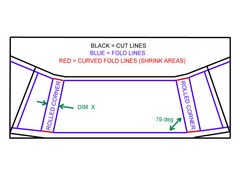
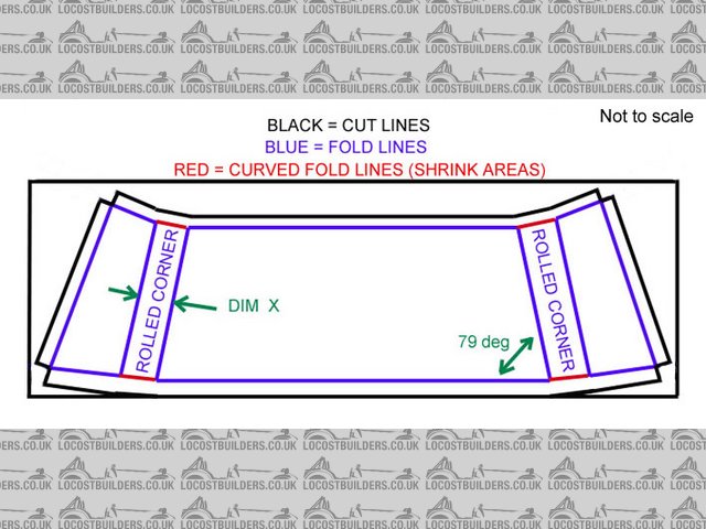
I have a book chassis (sort of) but 4" wider, so from the dash it narrows 11 deg per side, hence 79 deg in the drawing. Yours may differ.
Dim X is the metal required to go round the rolled rad.
My rad is 125mm all the way down to the nose cone, and is calculated using the formula Pi x D divided by 4.
i.e. 3.142 x 250 (twice rad) div 4 (90 deg of a circle)
785.5
______ = 196.375 mm (dim X)
4
A 5" rad would be:- 3.142 x 10 = 31.42 div 4 = 7.855 inches.
Even if you decide to have a slight curve to the top of your scuttle the cut out shape will still be a straight edge, till you come to the rolled
corner.
Tip. Holes cut near the edge of your wooden formers will allow you to G clamp the sheet to it. ( with a wooden batten on the outside to prevent
marking the sheet and hold it tight to the former while you tap the edge over.
I was able to start with the dash top edge with no need to cut. Overlap the former by 1"and clamp.
Bend the sheet round the former, cut the sheet back at the ends to 1" overlap and dress over/shrink.
You will need to notch out a square where the dash flange meets the chassis flange.
Surplus material can be cut off and remaining edges knocked over, shrinking the red areas.
I used an air nibbler with a spacer against my frame to give me a nice straight cut with my 1" extra to be dressed over.
Clear so far?
Cheers
Paul G
Edit to add:- The blue lines either side of "ROLLED CORNER" are the start and finish of the rad, and not realy fold lines.
[Edited on 2/1/10 by 907]
Rescued attachment scuttle layout.jpg
C10CoryM - 3/1/10 at 04:19 AM
Excellent help Paul. I appreciate you taking the time. I'm sure others will gain from this post as well.
I think what I will do is make a wood form and screw it to my wood table. Then get a paper template from it and transfer it to aluminum. Then bend
the aluminum over the wood form. I have enough aluminum for two chances. If I fail at both I will make the wood form into a buck for doing carbon
BTW I went with .040" T3 (halfhard) which is about 1mm. I think I will go a bit thicker next time though.
907 - 3/1/10 at 07:46 AM
quote:
Originally posted by C10CoryM
Excellent help Paul. I appreciate you taking the time. I'm sure others will gain from this post as well.
I think what I will do is make a wood form and screw it to my wood table. Then get a paper template from it and transfer it to aluminum. Then bend
the aluminum over the wood form. I have enough aluminum for two chances. If I fail at both I will make the wood form into a buck for doing carbon
BTW I went with .040" T3 (halfhard) which is about 1mm. I think I will go a bit thicker next time though.
You are more than welcome Cory.
It's always a pleasure helping some one willing to "have a go."
Before the Locost I had never seen an English wheel, shrinker, stretcher or a jenny, let alone used them.
My help and inspiration was Trev D, to whom I will always be indebted.
Screwing down to the bench sounds a good idea as the firmer it is the better the edges are to knock over.
Remember to space it up an inch or so (or work over the edge) as until the final end bends are done it will not sit flat.
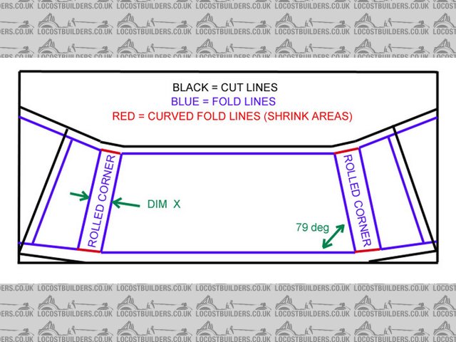
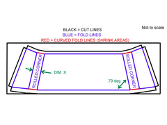
I've modified the drawing a bit and posted it below.
All the best.
Paul G
Rescued attachment scuttle layout2.jpg
C10CoryM - 6/1/10 at 06:01 AM
Well attempt #1 was a failure. I had too much flange, and the shrinker was hardening the metal too quickly. Eventually I tried to trim some of the
flange off in the corners because it was folding too badly, but then ended up with a crack that went to a visible part. Attempt #2 will be with
pre-trimmed and annealled corners. I dont think I will use the shrinker at all and just rely on the annealled aluminum to fold nicely. Or I could
just anneal it after every shrinking I guess.
When you start hammering, do you start at the corners or the flatter parts? I think I made it worse by starting with the flat parts. Ended up with
all my extra metal in one area.
907 - 6/1/10 at 03:11 PM
quote:
Originally posted by C10CoryM
Well attempt #1 was a failure. I had too much flange, and the shrinker was hardening the metal too quickly. Eventually I tried to trim some of the
flange off in the corners because it was folding too badly, but then ended up with a crack that went to a visible part. Attempt #2 will be with
pre-trimmed and annealled corners. I dont think I will use the shrinker at all and just rely on the annealled aluminum to fold nicely. Or I could
just anneal it after every shrinking I guess.
When you start hammering, do you start at the corners or the flatter parts? I think I made it worse by starting with the flat parts. Ended up with
all my extra metal in one area.
O Cory! Lesson one. There is no such thing as a failure.
Sometimes things don't turn out quite as well as we had hoped, but next time it will be better.
It's called a learning curve. Please don't give up.
Where to start? I'm asking myself the same question.
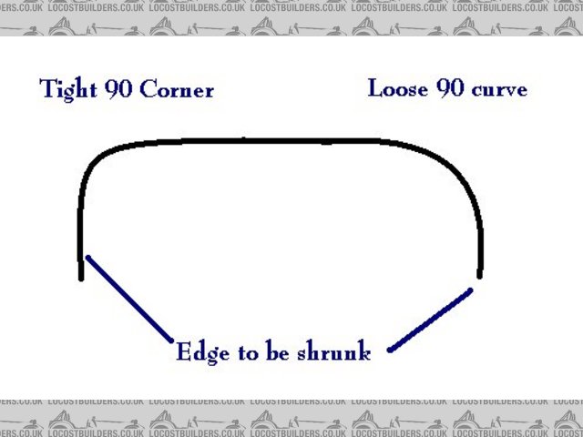
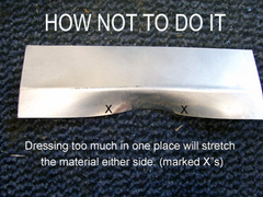
The technique is to tap the edge over to say 15deg and work along.
Go back to the start and work along again, this time to 30deg, but not as far.
Transitions should be gradual so that in no place does the edge go from 90deg to no bend at all, unlike the pic below.
I would start start with a centre line on the sheet corresponding with a centre line at the top centre of the dash former,
working outwards towards the scuttle corners, each time stopping a little shorter.
Another post to follow.
Paul G

Rescued attachment edge.jpg
907 - 6/1/10 at 03:37 PM
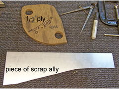
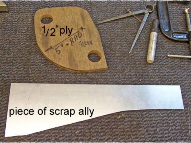
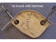
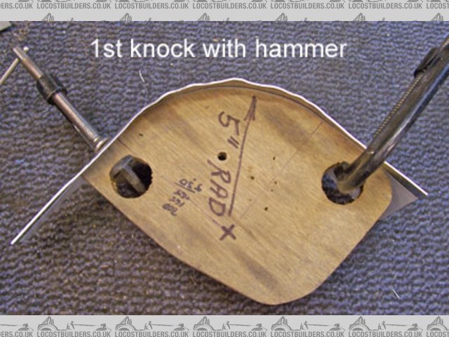
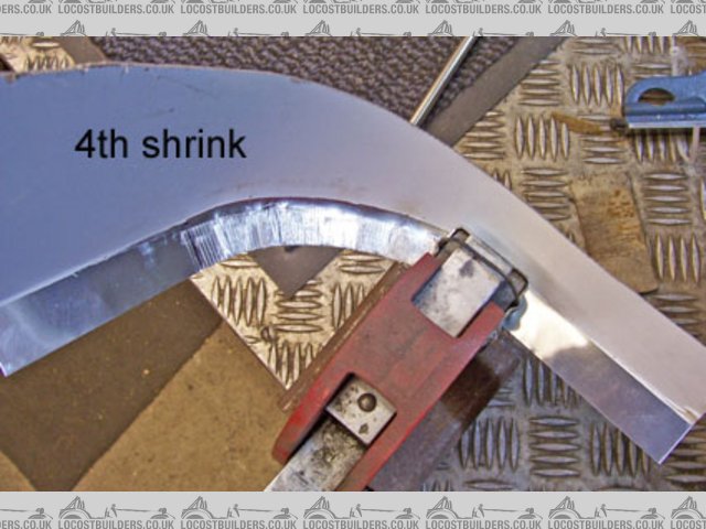
Since I cut my flange down at the corners I thought I might have a go on a piece of scrap to form a full 1" corner with the shrinker.
At least it keeps me off the streets.
The technique is to tap the edge over till it ripples, then shrink, working round the rad of the scuttle corner and down the side.
The holes in the 1/2" ply are useful for clamping with G's.
see pics and following posts.
Rescued attachment tc1.jpg
907 - 6/1/10 at 03:39 PM
Starting the rad.
Rescued attachment tc2.jpg
907 - 6/1/10 at 03:41 PM
A little progress.

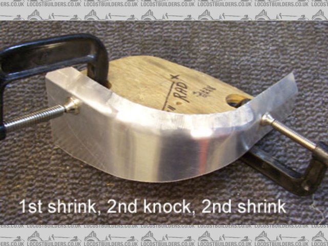
Rescued attachment tc3.jpg
907 - 6/1/10 at 03:43 PM
If your ally is hard then annealing could be done at this stage.
Rescued attachment tc4.jpg
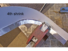
907 - 6/1/10 at 03:45 PM
A tad more with the hammer.
Rescued attachment tc5.jpg
907 - 6/1/10 at 03:49 PM
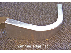
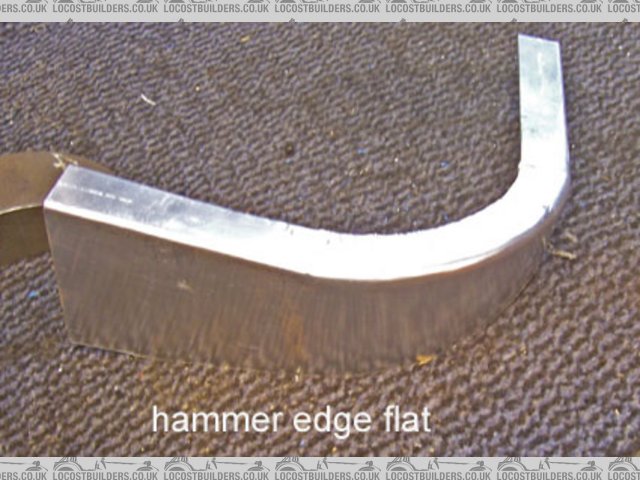
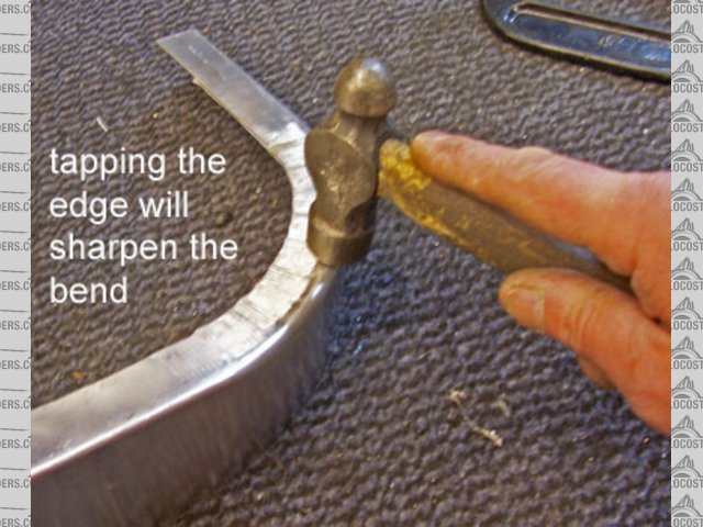
The corner of the bend may not be as sharp as you would like so a dress very near the edge will sharpen it.

Rescued attachment tc6.jpg
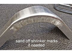
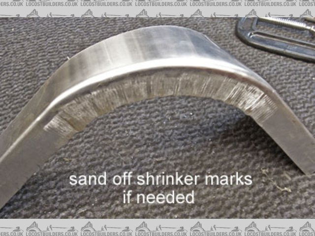
907 - 6/1/10 at 04:03 PM
The finished corner. Took about an hour including pics.
On a full scuttle you would do a bit to each side before un-clamping so progress would be quicker.
The shrinker marks can be taken out with a sanding block but mine are covered by the dash one side and the angle on the bulkhead side.
It looks out of shape in the pic but that's a trick of the light.
I hope this gives you a little more help and that number two is pleasing to the eye.
Cheers
Paul G
Rescued attachment tc7.jpg
TheGecko - 7/1/10 at 01:14 PM
Paul,
Thanks very much for posting that detailed tutorial. Two questions:
- when will your book "The Straightforward Guide to Metal Work for Locost Builders and other Like-Minded Nutters" be available?  You
have the rare combination of both actual skills (in this case, metalwork) plus the knack for explaining/illustrating it. Even a series of detailed
tutorial posts here on LB would be very welcome to me and, I'm sure, many others.
You
have the rare combination of both actual skills (in this case, metalwork) plus the knack for explaining/illustrating it. Even a series of detailed
tutorial posts here on LB would be very welcome to me and, I'm sure, many others.
- what is your opinion (and everyone else's for that matter) on using these techniques to make a set of front cycle guards? I don't want
ones with the edges rolled over very far so there wouldn't have to inordinate amounts of shrinking. I was thinking an MDF buck with routed
round-over edges. Do edges on on a part like that need wiring to be stiff enough?
Anyway, thanks again for your posts - they've been saved into my "Useful Tips & techniques" folder.
Dominic
907 - 7/1/10 at 03:59 PM
quote:
Originally posted by TheGecko
Paul,
Thanks very much for posting that detailed tutorial. Two questions:
- when will your book "The Straightforward Guide to Metal Work for Locost Builders and other Like-Minded Nutters" be available? You
have the rare combination of both actual skills (in this case, metalwork) plus the knack for explaining/illustrating it. Even a series of detailed
tutorial posts here on LB would be very welcome to me and, I'm sure, many others.
- what is your opinion (and everyone else's for that matter) on using these techniques to make a set of front cycle guards? I don't want
ones with the edges rolled over very far so there wouldn't have to inordinate amounts of shrinking. I was thinking an MDF buck with routed
round-over edges. Do edges on on a part like that need wiring to be stiff enough?
Anyway, thanks again for your posts - they've been saved into my "Useful Tips & techniques" folder.
Dominic
Hi Dominic,
Mmmm, that's a bit of a long winded name mate.
It would have to be a big book just to fit the title on.
Add to that the speed at which I type then I can only suggest that you don't hold your breath.
Cycle guards / mud guards / fenders (got to keep this thread international ) can be made this way but the tucks
that would reach back into the metal from the shrinker would need taking out with an English Wheel.
It's best IMHO to then wire the edges to give an appearance of thickness.
A thin edge of metal to me always looks "unfinished" somehow.
Now if I may I'd like to ask a question.
Since the forming of metal is such a fascinating subject, well it is to me, how come the few that have posted on this
subject are spread so thinly across the globe? Just a thought.
Thanks, and all the best,
Paul G
C10CoryM - 8/2/10 at 08:45 PM
Thanks for the good posts Paul and sorry for the delayed response. Life has been stupid lately.
My 2nd attempt was much better but still ended badly. I annealed all the edges, was scary watching it warp from the heat, but relieving to watch
it go right back to shape when quenching I'd never annealled a large piece before. The aluminum was soft enough I didn't bother trying
the shrinker again. Looked like I was getting a good enough edge without shrinking (I trimmed the flange off in the curved part). Since I will be
painting I can use a little filler to hide any folded parts.
Anyhow, I had it shaped over reasonably well until I realized I was getting way too much material in the middle of the scuttle. As I was shaping
it must have curved the piece more. Trying to work it so that there was less material there wasn't working and I ended with a giant dent there.
Crap. End of piece #2.
I know with some more practice I could get it. But I'm not willing to ruin that much aluminum. Im going to start making my forming buck into a
kevlar/carbon fibre buck once Im over this horrible cold.
Thanks for all the help. What I have learned I will be using elsewhere and Im sure others will too.
Cheers,
Cory
MikeRJ - 8/2/10 at 08:49 PM
quote:
Originally posted by 907
I hope this gives you a little more help and that number two is pleasing to the eye.
That's a great little tutorial, I've been itching to get myself a shrinker and have a go at alloy arches for a while.
907 - 8/2/10 at 11:37 PM
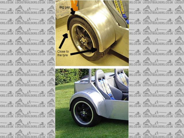
Sorry to hear your giving up Cory.
If it makes you feel any better I have my share of failures.
My first attempt at a rear wheel arch flew through the air like superman.
I cocked up the width of the sheet and it ended up more suitable for a bike.
Number two was crap. Sort of just didn't look right.
The ends finished in the middle of nowhere and it sort of hovered above the tyre.
I'm pleased with number three. When the car is viewed from the side the edge of the arch is an equal
distance from the centre of the wheel all the way round, while still allowing for suspension travel.
The bigger the challenge the more satisfaction you get when you get it right.
(Well, apart from painting. I get runs with garage floor paint.)
Cheers
Paul G
Mike, go for it mate. The worst thing that can happen is that you end up selling it on ebay.
In fact, if you pick up a second hand one you could even make a profit.
Cheers
Paul G

Rescued attachment rear arch 2and3.jpg


