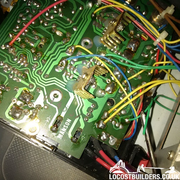
Other side of the circuit board, looks like it came from the D23, D24, D25, D26 etc region:
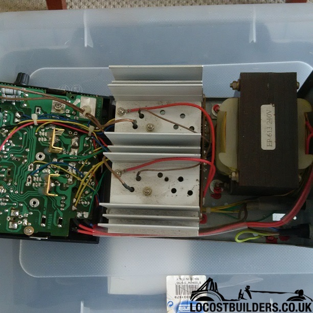
I have a Rapid PS3025 bench power supply and the variable output isn't working. I've taken it apart and found a disconnected wire but I
can't see where it should be connected.
It might not be the cause of the problem and I could have done that damage whilst dismantling but I can't be certain and there are no other
obvious problems.
Does any one have a Rapid PS3025 and wouldn't mind posting a picture of the circuit board so I can see where this wire goes??!
Google images doesn't throw up much in the way of images - any chance you can post some pics to see if we can help?
Detached green wire comes from the transformer and goes somewhere in the bottom corner of the circuit board.
Other side of the circuit board, looks like it came from the D23, D24, D25, D26 etc region:
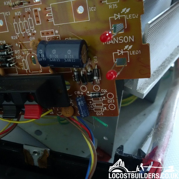
Looking at the circuit, my best guess is the pad circled below, which is the input to a half wave rectifier, the return of which is another green
wire. Look very carefully at the solder pad for evidence of a stub of broken wire sticking out.

Power supply wire
Even by Chinese standards the build quality of that is pretty shocking 
Even looking through a 10x loupe there is no wire sticking out but there is a little indent in the solder that looks right.....maybe.
Would that disconnected wire have anything to do with the variable outputs not working?
It could well be. It's an internal low current supply that may be powering the regulator circuitry itself, in which case it would most certainly cause problems.
OK thank you for the replies. I shall dig out the soldering iron and report back......
I agree that most probably its the pad mikerj has circled.
it also appears the circuit board has white circles where external connections go.
(and there's a second pad nearby for if using a bridge rectifier rather than single half wave rectifier. (all 4 diodes rather than just the one))
Variable output still not working. Any ideas why?
Are you getting nothing out of the variable outputs, or are they stuck at a fixed voltage? Did it just randomly stop working, or did it happen after it was heavily loaded?
Getting between -00.5 and -00.3 (takes a few seconds to change). Connected to a 12v circuit (car stereo in a briefcase with an inline switch) it shows
-00.0 when the switch is off then -00.3 when on regardless of how far the voltage dial is turned.
The permanent 5v and 12v outputs works fine.
I'm not sure what happened to it or if it was fine as it was my Dad's and he's not about anymore to ask.
[Edited on 6/10/15 by SALAD]
I agree with above, I feel that the correct pad has been identified.
Does the variable dial work. Its probably a variable resistor and can therefore easily checked to see it is is functioning.
Pretty sure I've got a couple of these in our test store at work. I'll see if I can dig one out tomorrow and have a look for you.
Ed.
I have one, made and sold by Manson as per the circuit board, badged by many.
there are some circuit diagrams on line for power supplies, apart from the missing wire,... I would check the tracks carefully and then inspect each
component for signs of heat stress (burning).
Then with a multimeter and some paper and a pencil it should be possible to follow AC from the transformer to the rectifier, and from there to the
voltage control circuitry. Some patience and it should be possible to identify the dead device.
hth,
Just to avoid any "Doh" moments, check that the current limiter control isn't set to zero!
Assuming that's ok then measure between the 0v output terminal and the collectors on the pass transistors (the thick red wire). You should be
getting a fairly high voltage here, possibly more than 30v DC depending on the design. If not then check for any thermal breakers on the heatsink
which may have gone open circuit. If there are relays to select different voltage taps from the transformer secondary (common on this type of supply)
then check for continuity through the relay contacts.
If you have plenty of voltage on the collectors, measure the voltage at the emitters (thick brown wires) with the voltage (and current) controls wound
up. If lots of voltage here, then check the current shunt resistors haven't burnt out. These will be high(ish) power resistors that are most
likely in the circuit between the power transistors and the output terminals.
If no voltage on the emitters, check the voltage on the base terminals (thin brown wires). If nothing on these the problem lies within the regulator
circuitry on the PCB, you'll need to trace it back. The base terminals of the main pass transistors will be driven by a medium power transistor
on the PCB, probably a TO220 packaged device
[Edited on 7/10/15 by MikeRJ]
I have checked the resistance on the dials and they appear to work.
The Volts dial goes between 0.00 and 8.13 and the Current dial goes between 0.01 and 4.29
I am way beyond my capabilities with what is what and how to test it now, even with the help so far, so it may take me a while to work through what
has been suggested.....whilst trying to avoid getting electrocuted.