
Alternator wiring double check.
MsD - 1/6/16 at 05:24 PM
I was wondering if anybody could help me double check that I'm going to wire my alternator in properly! Its the last stage of my conversion (for
a reason!) and im struggling with the basics...
I've just changed from a pinto to a zetec and in doing so fitted a smaller Kubota alternator.
My existing alternator (Bosch) had 3 wires- one warning light and two live feeds that came from my battery via my starter.
My new alternator has 3 electrical pins and one terminal on the side-
The terminal on the side is for a live (i will just use my existing lives)
I then have-
P (labelled as S on the Brise diagram but labelled P on the alternator label) is a battery sense. Presumably this can be left unused?
IG is ignition switched, presumably this just needs a new wire running from the fuse box?
L is a warning light, would my existing light work (with it being an ignition switched warning light)?
Instead of running an extra ignition live wire could I split my existing charge warning light wire to feed both my new warning light pin (L) and the
12v switched live pin (IG)?
I hope I've made this relatively clear, and what I'm saying is correct I know its a popular alternator to use so I was hoping somebody
could just clarify a few points before I wire it up and things start to smoke..
Thanks, Mark.
[img]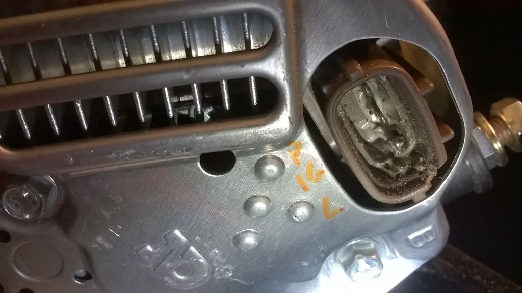 [/img]
[img] [/img]
40inches - 1/6/16 at 05:31 PM
I only wired IG and L on mine, charges at 14volts.
blakep82 - 1/6/16 at 07:23 PM
Did you get the proper connector, or how did you do it?
I'm struggling to find a connector at a reasonable price
40inches - 1/6/16 at 09:19 PM
quote:
Originally posted by blakep82
Did you get the proper connector, or how did you do it?
I'm struggling to find a connector at a reasonable price
I never found one for under Ł25 I used ,I think, 2.5mm crimp connectors and a power timer rubber boot. Works fine
britishtrident - 2/6/16 at 06:38 AM
One pin is an output signal that goes to the tintop ecu. It takes the form of a square wave, the duty cycle of which tells the ecu the electrical load
on the alternator so the idle speed and ignition advance can be adjusted to prevent the engine stalling. 50 percent duty cycle is zero load and 0
percent duty cycle signals the alternator is full field for maximum output.
If the engine ECU cannot use the signal there is no point in connecting it as it has no effect on the working of the alternator

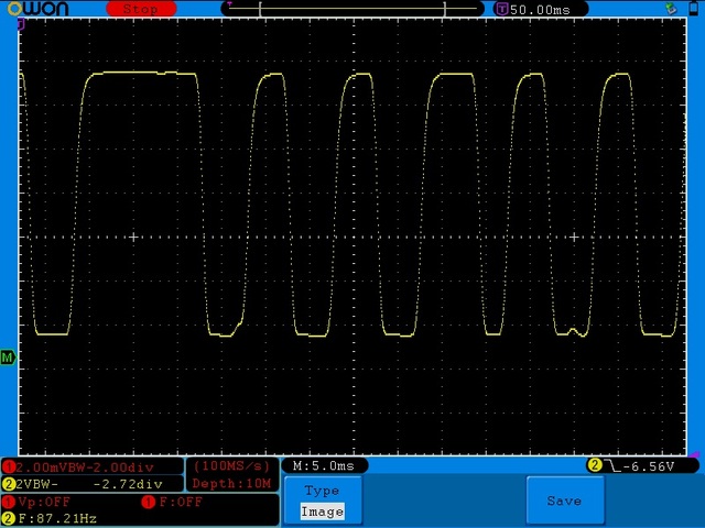
Denso Alt Duty Cycle Idle
MsD - 3/6/16 at 10:56 AM
Thanks for your help chaps.
Im going to use my existing warning lamp wiring to pin L and run a separate ignition live to the IG pin. Hopefully this will work... ill let you know
the outcome!
My alternator plug came with the alternator, Its still packaged up so I can get a part number if that helps?
Mark.
 [/img]
  [/img]