Tudor (Ted) Miron
|
| posted on 25/11/03 at 11:36 PM |

|
|
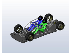
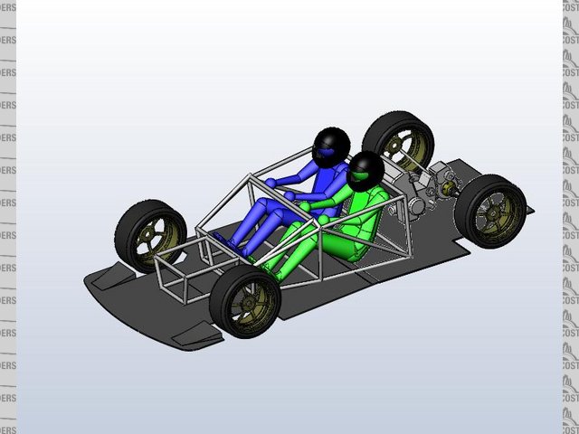
Initial packaging
Hi All,
Here's a pic. of initial packaging attempts.
Out of date allready  as usual. as usual.
Ted
Rescued attachment lmp01.jpg
|
|
|
|
|
sgraber
|
| posted on 26/11/03 at 02:38 AM |
|
|
Obviously many tubes missing...
My initial comment is that the sides are quite tall. That's good for rigidity, but hard to get in-out of.?
Graber
Steve Graber
http://www.grabercars.com/
"Quickness through lightness"
|
|
|
Tudor (Ted) Miron
|
| posted on 26/11/03 at 07:37 AM |
|
|
Yeah Steve tubes are missing. I guess that's the reason why it's named initial packaging and not triangulated chassis.
I agree that getting in and out could be a problem.... ecpecialy if Lady beside you is wearing skirt. Seriously I'm struggling here...
don't wan't to compromise rigidity. I guess that ultimate handling is a higher priority, at list at this stage.
Ted
|
|
|
locoboy
|
| posted on 26/11/03 at 09:10 AM |
|
|
Ted,
Here is my non engineering 2peneth worth,
The side rails could be lowered if you had an Ultima style full roll cage stye affair could they not? or are you going for the MKGT1 look with the
open top?
ATB
Locoboy
|
|
|
ceebmoj
|
| posted on 26/11/03 at 01:49 PM |
|
|
hi ted what CAD packeg are you using and how much does it cost I have fanced having a go at this but all of the CAD packeges are very expencive for
just having a play with
|
|
|
Alan B
|
| posted on 26/11/03 at 02:00 PM |
|
|
Educated guess...Solidworks?
|
|
|
kb58
|
| posted on 26/11/03 at 04:48 PM |
|
|
Where's the gas tank going?
|
|
|
Hugh Paterson
|
| posted on 26/11/03 at 10:52 PM |
|
|
front diffuser
Ted, just a hint the front diffuser wont work like that, I take it the fuel tank is under yer ass?
Shug
|
|
|
Tudor (Ted) Miron
|
| posted on 27/11/03 at 09:17 AM |
|
|
Yeah Alan it is Solid Works 2004. And yes fuel tank (ATL FC160) will be placed in very conventional way - like it's done on majority of single
seaters and sports cars - behind my ass. Obviously if placed near CG it doesn't alter weight distibution when full or empty.
Cheers
Ted
Oh and those two little things are NOT front diffuser it's errrrmmm.... what was left from front diffuser. Flours are flat for initial
packaging stage.
[Edited on 27/11/03 by Tudor (Ted) Miron]
|
|
|
suparuss
|
| posted on 27/11/03 at 11:29 PM |
|
|
i think you should go with tinted or mirrored visors on the helmets, and maybe those ears and mohicans that bikers stick on.
Russ.
|
|
|
cymtriks
|
| posted on 30/11/03 at 07:13 PM |
|
|
Chassis stiffness
Tudor,
You don't need to have such deep sides to guarantee stiffness but it will help. About 13 inches deep, as in the book, is fine for most chassis.
I've done some finite element studies of different chassis types (cobra, stratos, Lotus 23, Ultima, Lowcost, Elise) and also some fundamental
work on ladder and spaceframes to find out how basic design affects stiffness.
Project LMP, judged by eye, and the Lotus 23 chassis are pretty good for their weight.
The important things are probably as follows-
1) Fully triangulate the sides. Don't stop short of the front and rear suspension regions. In the book Lowcost chassis an extra diagonal
forwards of the FU tubes helps a lot.
2) Don't skip triangulating the engine bay properly. A Lotus 23 style single Y brace is the minimum. Check out a Caterham chassis which has two
long diagonals or my Double Y brace design in the pictures section. The Stratos gets round the need for anything more than simple triangulation by
using a fairly substantial beam around the bay top. Check out Ultimav12.ca for a very interesting set of stiffness mods to the Ultima.
3) Having made the car sides stiff don't forget to tie them together! Fully triangulate the front suspension region or use welded in steel
panels. Check out the mods I posted ages ago on the chassis section. The same goes for the back of the chassis. A Lotus 23 style bulkhead is very
effective as is a fully triangulated box around the transaxle.
4) Don't dismiss ladder frames. The Lotus Elise could be regarded as a very sophisticated ladder frame as its stiffness is largely derived from
two very stiff tubes in a ladder layout. Most kit car spaceframes are actually not stiffer than well designed ladder frames despite what many would
have you belive. A simple X braced ladder frame replacement for the book Lowcost chassis could actually be both stiffer and lighter if made from the
right size of tube.
Good luck with your project, let us know how you get on.
[Edited on 30/11/03 by cymtriks]
|
|
|
cymtriks
|
| posted on 1/12/03 at 08:24 PM |
|
|
Stiffness and Weight
Syd,
I'll switch of the computer and go through the numbers.
A 4x2 14 gauge RHS section 2 foot long weighs about 6.5lbs
A section of spaceframe side consisting of top and bottom rails (24 inches), one diagonal (25 inches) and a single vertical (11 inches) of 1x1 16
gauge weighs about 5.5lbs
A ladder frame member can thus be designed that is within 10% of the weight of an equivalent section of spaceframe in terms of size and
application.
Regarding beam stiffness you are completely correct. The spaceframe is better.
Torsional stiffness however is different.
Take a simple X braced frame consisting of two side tubes 90 inches long (the lowcost wheel base) and 40 inches wide (roughly lowcost). This is braced
by an X extending to within 10 inches of each end of the frame. Two spreader beams are fitted across the front and rear axle lines.
From Roark (The stress book)
The displacement of the X arms are calculated for a free end beam under a central load. For a 600lb central load on each diagonal of the X the
displacement is 0.1125. As there are two diagonals and the X centre is half way along both of them the relative displacement is a twist of 0.645
degrees or 1550ftlbs per degree.
Four tubes, two X arms and two side members are also going to be taking load in torsion over a 70inch length. This has a stiffness of 1468.
The tails of the chassis sides are a total of 20 (10 each end) long and have stiffnes of 2566 for both sides.
For twist, disregarding the X, we can take the reciprocals of 1468 and 2566, add, invert and we get 934.
Include the X by adding and we get 934 + 1550 = 2484ftlbs per degree.
In practice the bends in the chassis to hook over the rear axle and curve in at the front of car will reduce this figure as will adding suspension
turrets at the front which will flex relative to the chassis sides.
Computer back on!
My analysis, using FE, got 1355ftlbs per degree for a weight of 130lbs for a simple X braced ladder frame for a lowcost sized car. Not too far off the
above calcs given the closing remarks.
The Lowcost book gives about 1200 for 159lbs. Not as good for either weight or stiffness. However the ladder frame needs additional structures to
support the body work which add a little weight and the Book Chassis probably protects you a bit better, but not much better, in a side on crash.
My double Y braced design for the Lowcost gives over 2700 ftlbs per degree for slightly less weight.
A properly triangulated spaceframe is stiffer for its weight than a ladder frame.
However a ladder frame is generally simpler, not much heavier for a given stiffness, allows better access and engine bay room. Compared to most kit
car spaceframes it will be stiffer for its weight as few kit car spaceframes actually have really good triangulation.
A hybrid chassis with a ladder frame reinforced with regions of spaceframe may offer a very good basis for a home build.
[Edited on 2/12/03 by cymtriks]
|
|
|
Alan B
|
| posted on 1/12/03 at 08:34 PM |
|
|
2 feet of 4x2 x 14g weighs 6.46 pounds......where did 22 pounds come from?
Not nit-picking (this time.. )...it just seemed heavy so I checked.... )...it just seemed heavy so I checked....
|
|
|
cymtriks
|
| posted on 2/12/03 at 09:38 AM |
|
|
Mistake!
Alan,
Well spotted!
The original numbers were in cubic inches. I copied the wrong line of my calcs into the post and thus omitted the x0.283 to convert to lbs. I was in a
rush and didn't proof read it before hitting the post button.
I have now edited the post so it should make sense now.
|
|
|
cymtriks
|
| posted on 2/12/03 at 01:20 PM |
|
|
Just checking...
Syd,
By taper I was refering to the plan view of the chassis not the beams themselves. I'm not certain from your response if you got that part of my
assummed chassis or not.
You imply that you have done FE on real ladder frame chassis (and possibly spaceframes as well). We'd all be interested to hear more.
I have found sources of 4x2 14gauge in the past. I think one of the steel mills was called Red Roo. Unfortunately I lost the names of the sources due
to a computer fault some time back.
This is turning very interesting...
|
|
|
Tudor (Ted) Miron
|
| posted on 2/12/03 at 03:28 PM |
|
|
Hi All,
This thread is becoming interesting. First I do agree that actual "phisical" trosional tests are allways very usefull. FEA analyses are
not that simple and depend really much on software and aplication. I'm not an FEA guru but real gurus who make analysis for me tell this. Now
back to my chassis - the picture shown was not a picture of chassis but a picture of initial packaging that's the little difference.
I'll upload the chassis later as soon as it will be ready as well as pic's of FEA results. My chassis will be a bit anusual (relative to
locost ) it will be skinned using honeycomb panels. This is MUCH more efficient ( way stiffer and lighter) than simple tube triangulation (at
expence of added cost). It will be some kind of semymonocoque. Problem is that I'm not trying to build another overweight ill handling middy
I'm trying to design an ULTIMATE handling mashine  . .
Will see what will come out of it.... Don't want to look over.... erm.... selfbelieving but competition is not overly hard to beat -
sevensques are out of contention, than existing middys: XTR - an outdated design under modern looking skin. GT1 - not much to say but it's not
going to be highly sophisticated, Radical truely fast car but with some flows. What is good it's very well developed/tested/improved but
get's well beaten in straight contention on track with some proper sports cars.
Ted
[Edited on 2/12/03 by Tudor (Ted) Miron]
|
|
|
cymtriks
|
| posted on 3/12/03 at 01:07 PM |
|
|
An interesting chassis...
Try this site.
http://www.geocities.com/MotorCity/7630/index.html
Erwin has built a very stiff and reasonably light chassis using welded, riveted and bonded aluminium.
Very impressive.
Perhaps this approach would be suitable for finishing the structure shown at the start of this thread.
|
|
|
GO
|
| posted on 3/12/03 at 02:48 PM |
|
|
That, is a nice example of a not-so locost (about £7000 all up ). Very original.
|
|
|
suparuss
|
| posted on 3/12/03 at 07:56 PM |
|
|
cant believe he stuck it together with araldite. i know the frame is welded and all that, but it says in his trip to england page that his gearbox
mounting gave way, the first of many i would imagine.
may just be me but i wouldnt want to spend too much time driving it. alluminium is prone just going without warning, and there is no flexibility in
araldite either, i thought you were supposed to use special oven bake adhesive for ally? especially in somthing as critical as a car chassis.
body work looks very nice though, well impressive.
Russ.
|
|
|
Peteff
|
| posted on 3/12/03 at 10:38 PM |
|
|
That back end looks horrendous, like a fat arse. Aluminium has a finite lifespan doesn't it, prone to flex and fracture in everyday use?. Is Ted
developing a car for a race series or just a fun road car? There is a kit in December Which Kit?, the 5exi that he would be interested in, pity he,s
in Russia or somewhere. The only bad point about that one is the deep sides apparently.
yours, Pete.
yours, Pete
I went into the RSPCA office the other day. It was so small you could hardly swing a cat in there.
|
|
|
Peteff
|
| posted on 3/12/03 at 10:57 PM |
|
|
Scanned a picture of it.
 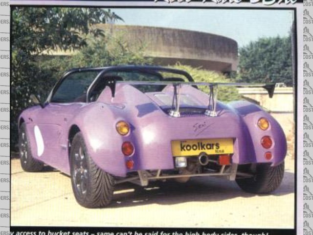
Rescued attachment marlin.jpg
yours, Pete
I went into the RSPCA office the other day. It was so small you could hardly swing a cat in there.
|
|
|
suparuss
|
| posted on 3/12/03 at 11:24 PM |
|
|
i saw a preview of that one some time ago and the frame looked either extrememly flimsy or unfinished, hte styling isnt too bad, but you seem to see
too many cars using peugeot style headlights these days.
Russ.
|
|
|
Alan B
|
 posted on 4/12/03 at 12:04 AM posted on 4/12/03 at 12:04 AM |
|
|
It is just me that thinks the 5exi back end fell out of the ugly tree.....the front is OK...but that back...
|
|
|
ned
|
| posted on 4/12/03 at 09:58 AM |
|
|
Alan,
it fell out of the ugly tree and hit all the ugly branches on the way down.
(agreed)
Ned.
beware, I've got yellow skin
|
|
|
Peteff
|
| posted on 4/12/03 at 12:29 PM |
|
|
I think that's a problem with all the rear(mid) engined kits. They concentrate on the bits everybody looks at first then just cover up the
engine. They all have too much going on at the back for that to be accomplished easily so they end up looking rear heavy with nothing to balance it at
the front. Just my thoughts on it. The deep sides are a problem on this car according to the write up but if they were cut down it would lose its
proportion and look like a dumbell, a lump at either end and thin in the middle.
yours, Pete.
yours, Pete
I went into the RSPCA office the other day. It was so small you could hardly swing a cat in there.
|
|
|