Viper
|
| posted on 20/11/02 at 07:33 PM |

|
|
quote:
Originally posted by johnston
the bosses morgan aero 8 as i said in another post has like a half and half thing they look like rod ends but are actually bushes
dot no where to get em or cost but if used will give u the adjustment the same as rod ends plus can be easily swapped u ever wish to do so but wont
give the harsh ride that rod ends do
therfore everyones a winner
if u can find em
[Edited on 20/11/02 by johnston]
TVR cerbera rear wishbones use em too
|
|
|
|
|
stephen_gusterson
|
| posted on 20/11/02 at 08:12 PM |
|
|
quote:
Originally posted by Jon Ison
wich will go 1st ????
a 10mm joint rated at 6000psi or
a 16mm joint rated at 4000psi ???
nuff said, its not the size that counts.....
Rod ends were originally developed for the aircraft industy. You can bet they are good quality, as would be the ones used in F1 teams.
The problem is with 'locost' is its tempting to get a bargain. You could well end up with a weak joint as you never saw the spec in the blind
search for a bargain.
Why use a 10mm joint if you could actually get the space to fit a 16mm or so one?
F1 joints are likely to be the best and get changed every race. Our ones are likely to get full of crap and not be checked for months.
going bigger is no harm.
atb
Steve
[Edited on 20/11/02 by stephen_gusterson]
|
|
|
Rorty
|
 posted on 20/11/02 at 10:49 PM posted on 20/11/02 at 10:49 PM |
|
|
God, I laughed!
I really stirred up a hornet's nest with that one. I've had so many emails.
Steve Gusterson: I tried replying to your emails, but they kept coming back.
Look, it's like this, not all rodends are equal. Some are of 2 piece construction, and some are 3 piece. Some are metal on metal, and some have
Teflon (PTFE) liners. Some are made from mild steel, some are stainless, and some are chrome moly etc etc.
Depending on the materials, a 1/2" National brand male rodend, for example, can have an ultimate radial capacity between 7,106lbs and 23,632lbs. You
pays your money, you takes your choice!
Generally speaking, I use the teflon lined ones for wishbones etc. The Teflon does add a little "stiction", but is not significant. The liner acts
as a wiper, and keeps all manner of sh1t out of the joint, and they never need lubricating. The metal on metal ones do need lubricating, and will
therefore attract dirt and dust, turning it into grinding paste, and the rodends will chop out in no time.
Everyone has asked where I got the nice cast T-ends. I'm not sure, but I think they're made in the States, as the ones I get here are identical to
the ones I used to get when I lived in England (with the exception of the colour of the polyurethane bushes).
I seem to remember buying them from one of the 32 Ford-fibreglass-hot rod type blokes in hampshire. Check out Street machine or Custom Car for
connections.
The T-ends are 5/8" UNF, and either straight or angled.
As for that glorious bit of welding I highlighted, I found it on a locost site, searching through the links, but I won't personally embarrass the
bloke any further.
Finally, to the imbecile who emailed me, saying he saw nothing wrong with the welding in the pic, and fired a good salvo of expletives at me for
having a go at someone's attempts to build their dream car, the name you used at the bottom of your email, doesn't match the one on the header! And,
if your welding really isn't as good as that in the pic, I suggest you double the premiums on your life insurance policy!
Cheers, Rorty.
"Faster than a speeding Pullet".
PLEASE DON'T U2U ME IF YOU WANT A QUICK RESPONSE. TRY EMAILING ME INSTEAD!
|
|
|
stephen_gusterson
|
| posted on 20/11/02 at 11:26 PM |
|
|
Hi
perhaps you typed the address in wrong, cos I have an always on cable connection thats been up and working for the last few hrs. address typos? (Im
well used to them being an exponent of them myself).
I have seen the 'bushed rod end' somewhere on the net - if I find it again I will let on.
Agreed, there are all those types of ends. Even similar types have wide variances of load ratings.
The ones I have are supposedly self lubricating.
As far as crap in them is concerned, a company in the UK called rota precision do boots and covers for them. The boots are really bulky, but the
covers are quite dinky. They are basically a washer with a concave rubber type seal that goes each side of the joint and forms a 'seal'.
The joints wont last forever, but on a car thats driven a couple thousand miles a year in the dry on well made british roads I dont think they will
suffer too massively.
atb
steve
[Edited on 20/11/02 by stephen_gusterson]
|
|
|
Rorty
|
| posted on 21/11/02 at 12:51 AM |
|
|
Steve, I actually just hit "reply", so I don't know which gremlin ate what.
Those sealing washers are called Seals-It, and aren't worth considering. The muck still gets in behind them, but doesn't like coming out! The boots
are similar.
I'll see if i can find a receipt for those bushed ends, which should give me an address of where I bought them. I'm a bit anal, I keep all the
receipts for each build, I just have to remember where I put the folder!
To anyone's knowledge, has a locost, or any other home built car ever been turned down by SVA on the standard of welding?
Cheers, Rorty.
"Faster than a speeding Pullet".
PLEASE DON'T U2U ME IF YOU WANT A QUICK RESPONSE. TRY EMAILING ME INSTEAD!
|
|
|
Rorty
|
| posted on 21/11/02 at 01:05 AM |
|
|
I just found a link for both adjustable arms, and adjustable bushes. Take a look at the specs of the materials used in the arms!
www.rdent.com/pages/parts.html
Cheers, Rorty.
"Faster than a speeding Pullet".
PLEASE DON'T U2U ME IF YOU WANT A QUICK RESPONSE. TRY EMAILING ME INSTEAD!
|
|
|
interestedparty
|
| posted on 21/11/02 at 08:45 AM |
|
|
Good find, Rorty
the full link is http://www.rdent.com/pages/parts.html
John
As some day it may happen that a victim must be found,
I've got a little list-- I've got a little list
Of society offenders who might well be underground,
And who never would be missed-- who never would be missed!
|
|
|
johnston
|
| posted on 21/11/02 at 12:02 PM |
|
|
surly those studed bush holders couldnt b hard to make or have an engineering firm to make up
|
|
|
stephen_gusterson
|
| posted on 21/11/02 at 07:53 PM |
|
|
quote:
Originally posted by johnston
surly those studed bush holders couldnt b hard to make or have an engineering firm to make up
looks fairly easy, but I would need to be absolutely confident of whovever welded them. I wouldnt trust me or my welder on such critical parts.
atb
steve
|
|
|
johnston
|
| posted on 21/11/02 at 09:21 PM |
|
|
thats why i said engineering firm
but have you not welded your own whishbones i wold call them fairly cruical 2
|
|
|
Rorty
|
 posted on 22/11/02 at 01:19 AM posted on 22/11/02 at 01:19 AM |
|
|
Johnston: Steve has a point. There's a difference between the combined strength of joints on a wishbone, and a single pivot like one of these
adjustable bushes. With the wishbone, the strength of the welds is shared out around several points, whereas it attaches to the car at only two
points....the adjustable bushes. If the welding on the fabricated adjustable bushes is in the least bit suss, that could lead to catastrophy.
Why doesn't one of you blokes who has connections with/proximity to a reputable engineering firm, approach them to manufacture these adjustable ends.
A simple jig to hold the two components securely for welding is all that's required. The correct materials, neatly TIG welded would be both strong,
and good looking.
These can then be used by the group as a whole, and possibly marketed even further afield, as the street rod types could also be interested in them.
I'm quite happy to do some CAD drawings to kick it all off. I would suggest using tube which is both common, and suitable for both the outer sleeve,
and the crush tube. The crush tube would be best made from stainless, as it won't seize onto the bolt, and won't need plating for asethetics either.
I've noticed from other posts on this list, the regular questions/problems regarding obtaining the polyurethane bushes. This would be a good
opportunity to source a standard size of PU bush, which I could incorporate into the drawing (if no body else with CAD want's to put their hand up
for the job).
Manufacturers such as Polybush, Powerflex, SuperFlex, etc. all make "universal" bushes, and AFAIK, SuperFlex supply a stainless crush tube as
standard.
Let me know if I can help.
Cheers, Rorty.
"Faster than a speeding Pullet".
PLEASE DON'T U2U ME IF YOU WANT A QUICK RESPONSE. TRY EMAILING ME INSTEAD!
|
|
|
Rorty
|
 posted on 22/11/02 at 01:30 AM posted on 22/11/02 at 01:30 AM |
|
|
These welded adjusters are used on those lardy great American cars by some of the drag racing fraternity for their four bar set-ups.
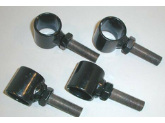 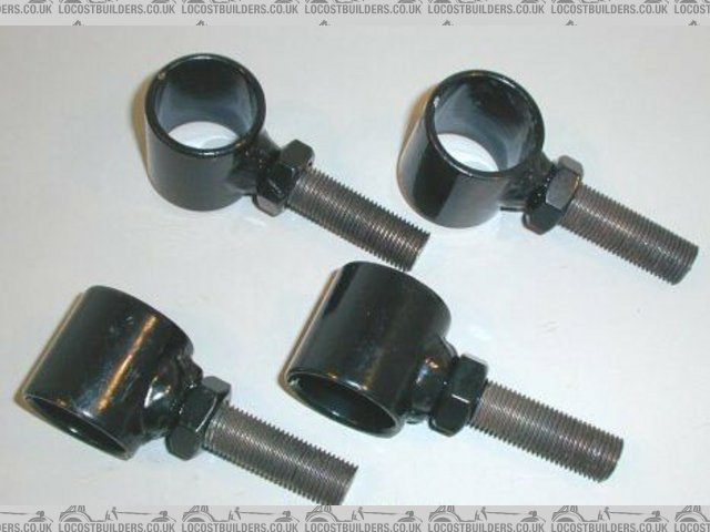
Rescued attachment studed_bushes.jpg
Cheers, Rorty.
"Faster than a speeding Pullet".
PLEASE DON'T U2U ME IF YOU WANT A QUICK RESPONSE. TRY EMAILING ME INSTEAD!
|
|
|
Rorty
|
 posted on 22/11/02 at 01:33 AM posted on 22/11/02 at 01:33 AM |
|
|
5/8" mild steel over-the-counter rodend, that was asked to do more than it was designed for.
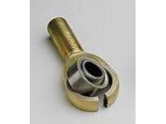 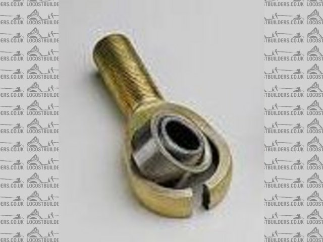
Rescued attachment broken_rodend.jpg
Cheers, Rorty.
"Faster than a speeding Pullet".
PLEASE DON'T U2U ME IF YOU WANT A QUICK RESPONSE. TRY EMAILING ME INSTEAD!
|
|
|
Viper
|
| posted on 22/11/02 at 02:25 PM |
|
|
If enough people ar interested in these i might be persuaded tofabricate some, same goes for mounting brkts etc, just let me know..
|
|
|
interestedparty
|
| posted on 22/11/02 at 03:41 PM |
|
|
quote:
Originally posted by Viper
If enough people ar interested in these i might be persuaded tofabricate some, same goes for mounting brkts etc, just let me know..
I think the problem there is going to be that people will want to know how much, and as presumably the more you make the cheaper they will be, you
will be into a chicken and egg situation. Why not do what a lot of manufacturers do, advertise a price at which you would be happy, then wait and see
if you get any orders. If you do, go ahead and make them, if not, nothing lost
John
As some day it may happen that a victim must be found,
I've got a little list-- I've got a little list
Of society offenders who might well be underground,
And who never would be missed-- who never would be missed!
|
|
|
Jon Ison
|
| posted on 23/11/02 at 08:15 PM |
|
|
Why use a 10mm joint if you could actually get the space to fit a 16mm or so one?
Could turn that one round, why use 16mm when 10mm will do, in my case cosmetics n weight, i dint want the "tractor" look around my rear end, but
each to his own.... myself, i am perfectly happy with my choice.....
4000 miles later no problems, a fair few of wich have been flat out on the track, and not too far off on the road...........
[Edited on 23/11/02 by Jon Ison]
|
|
|
stephen_gusterson
|
| posted on 24/11/02 at 12:02 AM |
|
|
i can understand that staetment Jon, apart from are not the joints all covered up by the arches ?
The big weight saving issues on road blasters always seem to need compromises. Saving 1 kilo on a set of joints on the risk of my life would not be
worth it for me.
atb
steve
|
|
|
stephen_gusterson
|
| posted on 24/11/02 at 12:06 AM |
|
|
quote:
Originally posted by johnston
thats why i said engineering firm
but have you not welded your own whishbones i wold call them fairly cruical 2
Yes, I have done my own bones and you should see em - well over engineered! The top ones im doing again cos I just dont like the look of them, but
they would never break.
As mine are covered up in my morgan replica, they are made of inch rhs, not tube. The rod ends scre into big 16mm threaded blocks, welded between two
3mm steel plates, into which the inch rhs goes. Essentially they are solid triangles - not just a Y shape like a book locost.
I like the idea of replacing my rod ends with adjustable joints and I think I have a design that would be aeasy to do at home and wouldnt suffer the
weld stresses that Rorty and I suspect would occur. If I can sketch the idea up i will post it.
atb
steve
|
|
|
stephen_gusterson
|
| posted on 24/11/02 at 12:40 AM |
|
|
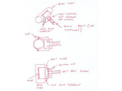
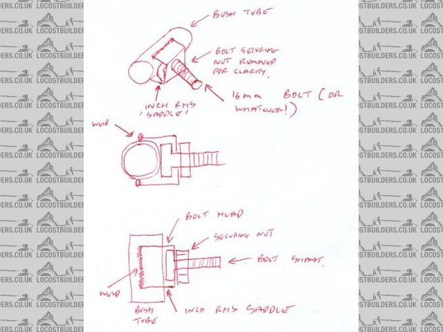
joint idea
Unless you are an ace welder (im not) just welding a stud on the tube might tend to cause it to rip out. There is a lot of leverage and shock loads
involved. Also, as steel for bolts etc is high tensile high grade, I wonder what welding that does to its strength?
My idea basically uses a machine screw, bolted to a U shaped saddle, that is then slipped over the tube and welded down the whole length of the tube.
A nut is used to hold the bolt in place.
The head of the bolt is hard against the tube. If there are no concerns on welding the bolt head, this could also be welded to the tube.
Belt and braces I recon.
I cant see how this would be anywhere near as stressed as welding a stud on at one small point. Providing that you can get inch rhs over your bush
tubes, its something you can do easily in the garage. If the bolt head is too big, you could cut some bigger flats on it to allow it to go in the rhs
channel.
atb
steve
[Edited on 24/11/02 by stephen_gusterson]
Rescued attachment joint.jpg
|
|
|
Wadders
|
| posted on 24/11/02 at 12:47 AM |
|
|
neatly TIG welded would be both strong, and good looking
Not strong enough though,the ones in your pic have been either Mig or stick welded, with a fillet of approx 6mm,if i was stick welding them i would go
for a low hydrogen rod, to increase strength. Mig welding would be fine. The weak point in the design is actually the tube itself,as it is quite thin
wall,any undercutting of the weld could lead to joint failure, but welded properly the weld would actually be stronger than the tube itself. using TIG
you would struggle to attain a suitable sized weld .
|
|
|
johnston
|
| posted on 24/11/02 at 10:59 AM |
|
|
why doesnt someone that knows what their talkin about work out what load would go through the rod ends on trailing arms and wishbones on a book locost
for the most popular set ups
1.6 x flow
2.0lt pinto
and a bike engine (no idea wats most popular)
and cossie
then i'm sure chris w will make a file section if we all ask nicely
and then the nice very smart person could post said list with the usual disclaimers
then us not so smart people could decide weather to go for cheaper but big rose joints or smaller and more expensive ones
then it will be a bit more than guesswork when any future builder start building or any body else can see their usin underrated joints will know to
change up.
|
|
|
interestedparty
|
| posted on 24/11/02 at 11:14 AM |
|
|
I really like Steve's design, and M16 bolt would be a good choice because the pitch is 2mm, so each 180 degree turn would be 1mm, handy for
adjustment purposes.
Also the design would be quite easy to make and keep straight, the design means that the bolt comes out perpendicular to the tube, something that
would require a jig otherwise.
Well done
John
As some day it may happen that a victim must be found,
I've got a little list-- I've got a little list
Of society offenders who might well be underground,
And who never would be missed-- who never would be missed!
|
|
|
stephen_gusterson
|
| posted on 24/11/02 at 12:26 PM |
|
|
quote:
Originally posted by interestedparty
I really like Steve's design, and M16 bolt would be a good choice because the pitch is 2mm, so each 180 degree turn would be 1mm, handy for
adjustment purposes.
Also the design would be quite easy to make and keep straight, the design means that the bolt comes out perpendicular to the tube, something that
would require a jig otherwise.
Well done
John
Oh, thanks for that. Had a good idea for once
I strongly think I might have a go on my car with those. The 16mm rose joints on my car concern me in two areas. As Liam points out in an earlier
post, F1 cars use rose joints 'flat' in plane with the road. On a locost using them in front suspension, to get the right movement, you need to run
them 90 degrees to that. This puts braking loads into them sideways, which tries to force the bearing out of the shank. The joints have about 15 - 20%
load rating this way.
Also, my rear swing arm design puts a lot of load on the outer joint, and looking at the pic of the failed joint Rorty has put up, I can imagine that
kinda failure occuring.
Going with my design gives std locost type loading on braking at the front, and as per the back, the weakest point is likley to be the 16mm bolt
shank. That can always be made bigger if I was still concerned.
ATB
Steve
|
|
|
stephen_gusterson
|
| posted on 24/11/02 at 12:31 PM |
|
|
quote:
Originally posted by johnston
why doesnt someone that knows what their talkin about work out what load would go through the rod ends on trailing arms and wishbones on a book locost
for the most popular set ups
1.6 x flow
2.0lt pinto
and a bike engine (no idea wats most popular)
and cossie
then i'm sure chris w will make a file section if we all ask nicely
and then the nice very smart person could post said list with the usual disclaimers
then us not so smart people could decide weather to go for cheaper but big rose joints or smaller and more expensive ones
then it will be a bit more than guesswork when any future builder start building or any body else can see their usin underrated joints will know to
change up.
Possibly cos we are mostly amateurs, and those on here that do have simulation software probably find its not part of their build so why bother.
Perhaps cymtricks will prove me wrong!
I still cant understand why we have to apply all that extra science when you could just simply use a bigger joint?
What the heck do you really lose by just using a bigger joint????
1 kilo weight? Cut out burgers for a week
atb
steve
|
|
|
Alan B
|
| posted on 24/11/02 at 01:49 PM |
|
|
quote:
Originally posted by stephen_gusterson
......Possibly cos we are mostly amateurs, and those on here that do have simulation software probably find its not part of their build so why
bother.
Perhaps cymtricks will prove me wrong!
I still cant understand why we have to apply all that extra science when you could just simply use a bigger joint?
Steve, a lot of the problem is deciding what "real-world" loadings your part will be expected to take. The maximum loadings for cornering, braking,
acceleration...times a safety factor....yes, of course. But, how much more? how much of a shock loading over and above this should we design for?
Certain levels of loading can only be reached in a crash, but do you want it to stay intact then? or maybe bend/break and give a little?
All difficult questions and many assumptions.
When you have a number (or numbers for different loading scenarios) you wish to achieve you can move on to the analysis. The part analysis is
relatively easy, often easily done without FEA software for simple parts.
In reality it is easier to either (a) go bigger (as you suggest) or (b) see what works for others.
I guess what I'm saying is figuring out the loadings to design for is harder than analysing the part, conversly picking out a part with "x" pounds
design load rating can be difficult..."x" may seem huge or way overkill....but until you have some decent figures to rate it against you just don't
know.
If anyone with motor industry part design experience wants to step in with some actually used design figures..........
Actually, "Racing and sports car chassis design" by Costin and Phipps does have some typical design figures in it's appendix. May be worth tracking
down a copy if anyone is interested.
|
|
|