mad-butcher
|
| posted on 23/6/09 at 07:25 PM |

|
|
measuring caster angle
evening all
need help in measuring caster angle. what points on the sierra upright do i take the measurment through. must add I'm using eccentric mushrooms
with balljoint fully forward to give maximum caster.
tony
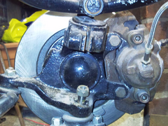 
Rescued attachment Photo0155.jpg
|
|
|
|
|
matt_claydon
|
| posted on 23/6/09 at 07:41 PM |
|
|
Caster is the angle from the vertical of the line between the centres of the top and bottom balljoints.
Rotating the mushroom only affects KPI - since it has no effect on the balljoint position, it has no effect on caster.
|
|
|
StevieB
|
| posted on 23/6/09 at 08:02 PM |
|
|
The castor line remains the same, but the relationship to the KP axis is changed, thus giving the same effect as adding more castor (ie, the lower
ball joint centre is moved forward in relation to the KP axis).
If you want proper castor adjustment, the best bet is to go for the upper wishbones from Wozsher (or make your own).
|
|
|
chrisg
|
| posted on 23/6/09 at 08:03 PM |
|
|
Whilst rotating the mushroom will affect KPI (except at the fully forward and fully rearward positions) that is not it's function.
The caster angle cannot be adjusted by moving the mushroom, however having it in the forwardmost position increases the mehanical trial of the set up
and so increases self centring. Effectively it moves the axle centreline in front of the line between the top and bottom balljoints, rather than
behind it. it's a good compromise given the limitations of the Sierra upright.
Increasing the caster by making new wishbones or moving the top wishbone pivots rearward brings it's own problems including inducing a tendancy
for the contact patch to move on to the sidewall of the tire and for the tyre to "flop" from side to side rather than a smooth steering
transition.
Cheers
Chris 
Note to all: I really don't know when to leave well alone. I tried to get clever with the mods, then when they gave me a lifeline to see the
error of my ways, I tried to incite more trouble via u2u. So now I'm banned, never to return again. They should have done it years ago!
|
|
|
StevieB
|
| posted on 23/6/09 at 08:05 PM |
|
|
I would add that as far as aiding self centering goes, it's still nothing short of poor on the Indy. I've had to go for rediculous
amounts of toe out to even get the car to attempt self centering.
|
|
|
mad-butcher
|
| posted on 23/6/09 at 08:12 PM |
|
|
StevieB it was me that wozsher made the wishbones for, what I want to know is how I check the caster angle so I can set both sides up the same while
taking into account the comments in the second paragraph of chris's reply.
tony
[Edited on 23/6/09 by mad-butcher]
|
|
|
BenTyreman
|
| posted on 23/6/09 at 08:48 PM |
|
|
Measure the height of the two balljoint knuckles. Mark a spot on the rear wing at the average of these two heights. Measure the distance from the spot
on the rear wing to the knuckles on the two balljoints. This should give the (approximate) set-back of the top wishbone.
Rotating the mushroom changes the kingpin inclination (once you correct the camber angle) and the castor trail. It has zero effect on the castor
angle.
|
|
|
Hellfire
|
| posted on 23/6/09 at 09:30 PM |
|
|
We measured our castor angle by using a plumb-bob. With the car on a level surface, we removed the wheel, the upright and both top and bottom
balljoints. We used masking tape on the lower wishbone and plotted a line perpendicular to the chassis through the centre of the hole for the
balljoint. We then drew another line 25mm further back. The plumb-bob was then fastened on the top wishbone so that it was suspended through the
centre of the hole for the top balljoint. The wishbone was then positioned within the bracket so that the plumb-bob was directly over the 25mm setback
line and the spacer dimensions were measured on the brackets to enable spacers to be made up.
Once the spacers have been made, the top wishbone can be fastened up tightly and checked again in the same way. Any slight adjustment needed can then
be made by screwing the rosejoints in or out as required.
Phil
|
|
|