Irony
|
| posted on 2/2/11 at 01:36 PM |

|
|
Rover V8 Cooling Diagram
I am a little bit confused about the water cooling system in my Rover V8 with Carbs. Can you intelligent types join up the pieces for me?????????
Thanking you in advanced.
P.S Letters J and K are threaded holes into the radiator. I suspect for temperature sensors.
 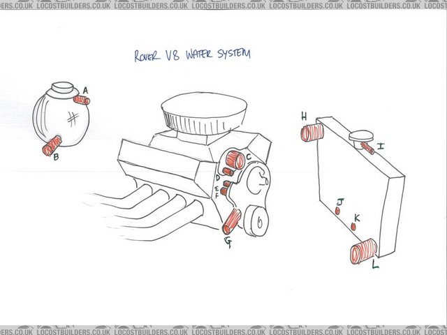
Rover V8 cooling diagram
[Edited on 2/2/11 by Irony]
|
|
|
|
|
blakep82
|
| posted on 2/2/11 at 01:48 PM |
|
|
C to H
L to G
B also to G
D possibly to A
I shouldn't need to go anywhere, as if you're using a header tank you shouldn't really have a pressure cap on the radiator, so
nothing should come out of it
E &F connect to each other unless you're using a heater inside, in which case they'd go there
J&K temp sensors as you say
think that covers everything. i may be wrong on some things there, but i'd like to see from others if i'm right 
with that radiator though, i'd have an expansion bottloe in the end of I, so any fluids that come out get collected in a bottle, and sucked back
in when the system cools, and not have a header tank
________________________
IVA manual link http://www.businesslink.gov.uk/bdotg/action/detail?type=RESOURCES&itemId=1081997083
don't write OT on a new thread title, you're creating the topic, everything you write is very much ON topic!
|
|
|
hearbear
|
| posted on 2/2/11 at 01:49 PM |
|
|
I think K and J are for an oil cooler
|
|
|
r1_pete
|
| posted on 2/2/11 at 01:55 PM |
|
|
I should go to A providing A is below the pressure seal, in which case the cap on the rad should be plain not a pressure type, the header tank should
have a pressure cap.
If I remember correctly there is a steel pipe running under the inlet manifold which fed the heater, is that D?
|
|
|
Irony
|
| posted on 2/2/11 at 02:07 PM |
|
|
quote:
Originally posted by r1_pete
I should go to A providing A is below the pressure seal, in which case the cap on the rad should be plain not a pressure type, the header tank should
have a pressure cap.
If I remember correctly there is a steel pipe running under the inlet manifold which fed the heater, is that D?
D comes from the same place as the Thermostat housing on the manifold.
|
|
|
Irony
|
| posted on 2/2/11 at 02:45 PM |
|
|
quote:
Originally posted by hearbear
I think K and J are for an oil cooler
I don't know. The radiator came from a TX1 taxi. I shall have to look. I don't think so but you could be right.
|
|
|
AdamR
|
| posted on 2/2/11 at 02:49 PM |
|
|
G to L (bottom rad hose). Tee-in B (header feed) and D (thermostat bypass) here also.
C to H (top rad hose).
E & F are for heater. Use for a heater or blank off or connect together. You could probably connect B in here instead of into the bottom hose.
As said you don't need a pressure cap on you rad as you should have one on your header tank. You may be able to use I as an air bleed for the
rad, in which case you should restrict the hole to 2-3mm and plumb in to A. You should also have n air bleed take off on your inlet manifold
somewhere, which should also be plumbed in to A.
No idea about J & K. I would not advise using for temp sensors or fan switch as they are at the bottom of the rad and therefore the coolest point
in the system.
[Edited on 2/2/11 by AdamR]
|
|
|
r1_pete
|
| posted on 2/2/11 at 04:06 PM |
|
|
99% sure J&K will be auto transmission cooler connections.
|
|
|
Paul (Notts)
|
| posted on 2/2/11 at 05:03 PM |
|
|
Have a close look at E anf F...
on mine one of these had a core plug in it so it was not used. The other had the bypass from the thermostat connected to it (D)
D can also be fitted to the botton hose which connects G and L . this returns cooled water to the pupm to be circulated round the engine.
C goes to H to take hot water back to the rediator to be cooled bown. Any temp sensor for a fan swithch can be fitted to this hose.
J and K connect together or block off - not sure what they are.
I to A
B to the G_L hose to top up and aloow for expansion of coolant.
AS ADAMR says ......

|
|
|
Irony
|
| posted on 2/2/11 at 05:50 PM |
|
|
Seems that the radiator does include a transmission oil cooler. Some Rover V8 I have looked have remote oil coolers so perhaps I can utilise these
ports.
|
|
|
mark chandler
|
| posted on 2/2/11 at 05:59 PM |
|
|
Most important, a pipe you have not shown
On the inlet at the top between the carbs will be a small rusty barbed tube, this must go via a 4mm bit of pipe to a new barbed equivilent that goes
into the top of radiator.
Without this you will end up with overheating issues, its there to vent air from the inlet.
[Edited on 2/2/11 by mark chandler]
|
|
|
Paul (Notts)
|
| posted on 2/2/11 at 06:49 PM |
|
|
Not on the Elberock manifold that he is using.
|
|
|