ffrgtm
|
| posted on 26/7/12 at 09:42 AM |

|
|
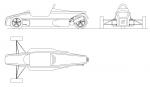
MNR Cad Model
Slowly making some progress....

|
|
|
|
|
loggyboy
|
| posted on 26/7/12 at 11:14 AM |
|
|
Ooo copyright..... lol (joke)
Mistral Motorsport
|
|
|
designer
|
| posted on 26/7/12 at 12:35 PM |
|
|
That's really good. But why?
|
|
|
loggyboy
|
| posted on 26/7/12 at 01:03 PM |
|
|
quote:
Originally posted by designer
That's really good. But why?
To be fair I did exactly the same (well started) when I bought the striker, just to have as a record and as an 'exercise' for me.
Mistral Motorsport
|
|
|
D Beddows
|
| posted on 26/7/12 at 01:27 PM |
|
|
quote:
That's really good. But why?
I think everyone who can use CAD has done it at least once (including me) - you come to realise it's a completely pointless exercise really as
it takes so long to measure (or get measurements for) parts and then model them (apart from the chassis) you may as well just build the car  . Which
probably explains why so few people ever bother finishing their CAD models properly! . Which
probably explains why so few people ever bother finishing their CAD models properly!
There are notable exceptions however and if you enjoy it then why not 
|
|
|
ffrgtm
|
| posted on 26/7/12 at 06:02 PM |
|
|
Thanks guys, and I'll agree it can be a huge waste of time... this chassis took forever with all of the tube bends.
I did it simply because I'm running fea to check the results of some frame tweaks... also going to play with the geometry. I have some software
than can iterate pickup points to optimize lap simulation times... may as well use it!
|
|
|
ffrgtm
|
| posted on 2/8/12 at 11:48 AM |
|
|
I've gone a bit further with my cad model...
I've put together a very basic torsional rigidity test using the fixed and loading conditions shown in the wireframe example. I currently have
the frame modeled only with beam elements which I don't feel give a very accurate representation. I did my best to model the unusual weld beads
that join the bent tubes in an x-configuration... but even normal welds are difficult to simulate.
I have most of the suspension modeled and will eventually run a more realistic simulation... as is the loads aren't entering the frame very
accurately... nor are the real suspension structures being tested. Before I get to that point I would like to have the frame modeled with shell
elements so I can include the original gussets, suspension tab sheet metal, and test ideas.
The results shown here are displacement, URES is nothing more than sqrt(x^2+y^2+z^2). I loaded each of the two points with 500N in opposite
directions, while the fixed conditions in the rear allowed individual rotation but no translation.
If anyone has any specific or ideas or requests I'd love to hear them. Like I said... this first test isn't very accurate but it
suggests room for improvement.


|
|
|
loggyboy
|
| posted on 2/8/12 at 12:34 PM |
|
|
Rollcage bars look very skinny, if they are being used as part of the calcs?
Mistral Motorsport
|
|
|
ffrgtm
|
| posted on 2/8/12 at 12:35 PM |
|
|
Heres one where I tried some different loading conditions and requested a deformed (exaggerated) result. It helps you visualize how to improve the
design.

|
|
|
ffrgtm
|
| posted on 2/8/12 at 12:40 PM |
|
|
quote:
Originally posted by loggyboy
Rollcage bars look very skinny, if they are being used as part of the calcs?
I measured them to be 38mm in diameter. I found msa regs that state either 38 or 45mm so I just used the wall thickness from the 38 spec. I might have
perspective mode on in that photo as well... that could make it look a little funny.
Anyways, I'm not using the cage in the calcs yet because I have having a hard time getting the mesh where the cage is welded to the gussets on
the frame. I hope to get to that point eventually... although I feel like some things could be done to better take advantage of the cage.
|
|
|
loggyboy
|
| posted on 2/8/12 at 12:43 PM |
|
|
Main rollbar and diagnols should 45mm min IIRC.
Mistral Motorsport
|
|
|
ffrgtm
|
| posted on 2/8/12 at 12:48 PM |
|
|
Crap I'll have to check my frame again.... while we're on the subject, you wouldn't happen to know which 1" diameter tubes are
the lighter 18 gauge rather than 16 gauge would you? 
[Edited on 2/8/12 by ffrgtm]
|
|
|
loggyboy
|
| posted on 2/8/12 at 01:24 PM |
|
|
16 gauge is 1.5mm
18 gauge is 1.2mm
So the 18 is lighter (no idea why the higher number is the thinner?!)
http://en.wikipedia.org/wiki/Sheet_metal#Gauge
[Edited on 2-8-12 by loggyboy]
Mistral Motorsport
|
|
|
ffrgtm
|
| posted on 2/8/12 at 01:30 PM |
|
|
 I mean which tubes in the MNR chassis are the 16 gauge and which are the 18 gauge. MNR uses the 18 gauge in less critical spots to save weight,
I just cant tell exactly which spots those are since they're the same OD. I mean which tubes in the MNR chassis are the 16 gauge and which are the 18 gauge. MNR uses the 18 gauge in less critical spots to save weight,
I just cant tell exactly which spots those are since they're the same OD.
|
|
|
Agriv8
|
| posted on 2/8/12 at 02:38 PM |
|
|
I should be able to get that info from MNR next time I am over.
I would also say the plates for the top front arms will strenthen the front, and the rear plate that the hoops bolt onto will also help.
but i am impressed you must have hours even days in the model.
ATB agriv8
Taller than your average Guy !
Management is like a tree of monkeys. - Those at the top look down and see a tree full of smiling faces. BUT Those at the bottom look up and see a
tree full of a*seholes .............

|
|
|
ffrgtm
|
| posted on 2/8/12 at 03:33 PM |
|
|
Thank you agrv8, and I appreciate the compliment! If you do find yourself over at their shop, could you please also snag the wall thickness of the
smaller diameter (0.64 about) tube that they use for the front x?
And it's true that I have way too much time into this thing so far.... my CAD skills have gotten a lot better though so it's a
"career skill investment"
I definitely do agree that I've left out some critical parts of the frame... to be honest I do have most of that stuff in my model, but getting
it to mesh with beam elements is another story... I had to suppress them and just run it before I went insane. I pretty much had to start over from
scratch and fully define all my sketches and treat everything as surfaces.
On a side note did you know that the $4000 cad workstation graphics cards ATI and Nvidia sell are exactly the same as their $200 models? The only
difference is what drivers they allow you to install...
Solidworks is particularly stupid... I literally just changed the name of my graphics card in my system properties to the FireGL equivalent and models
are running 10 times faster.
I need to sleep more often.
|
|
|
loggyboy
|
| posted on 2/8/12 at 03:45 PM |
|
|
quote:
Originally posted by ffrgtm
I mean which tubes in the MNR chassis are the 16 gauge and which are the 18 gauge. MNR uses the 18 gauge in less critical spots to save weight,
I just cant tell exactly which spots those are since they're the same OD.
Sorry I miss read your post! I thought you said which is lighter, not which ones are the lighter ones!
Mistral Motorsport
|
|
|
Agriv8
|
| posted on 2/8/12 at 04:26 PM |
|
|
Crap -hics drivers are the Whiches work, it will all be to do with Opengl support and other maths that the processor passes to the card to do rather
than itself. but yes graphics cards and costs are a funny thing and confising matter.
The small tube at the front ( is it 12/13mm my chassis is to old ) is thick walled poss 2 mm maybe upto 4mm as I have used the tube for other
things
I am sure Marc will be happy to assist as its always good to have indipendant maths backing up his own work. The Full Cage is also very structural if
fitted !! regardless of the Double bend !!
Keep up the Good work and keep us updated with your analysis.
PS a couple of tube apears to have disapeared where the prop would travel to the Reverse box
ATB Agriv8
Taller than your average Guy !
Management is like a tree of monkeys. - Those at the top look down and see a tree full of smiling faces. BUT Those at the bottom look up and see a
tree full of a*seholes .............
|
|
|
MK9R
|
| posted on 7/9/12 at 08:48 AM |
|
|
Great work, very interesting
Cheers Austen
RGB car number 9
www.austengreenway.co.uk
www.automatedtechnologygroup.co.uk
www.trackace.co.uk
|
|
|
ffrgtm
|
| posted on 18/9/12 at 08:42 AM |
|
|
Thank you
Unfortunately work is at a bit of a standstill right now while I develop the PDM for my team's FSAE car... I'm taking care to make sure I
can print an extra pcb or two and use it for the MNR as well

|
|
|
ElmrPhD
|
| posted on 16/10/12 at 09:46 AM |
|
|
Hey structural engineers...
My car-engined-car's RT+ chassis lacks the tube that runs from left to right under the gearbox, where the bell-housing ends (middle of
transmission). Every other chassis I see on the 'net has something there. Should I be concerned?
Directly above that, where all others seem to have a permanent bar, I DO have a bar that I am to bolt in after the drive train is installed.
I do intend to beat the poo out of this car at the track, so I'm wondering if I need to add a brace (back) under the gearbox. Or does the
presence of a factory full roll cage omit the need for that lower cross tube?
Thanks for any advice.
Cheers,
Steve, in the NLs
|
|
|
big_l
|
| posted on 31/10/12 at 12:38 AM |
|
|
None of this takes into consideration the engine on a BEC us used as a stressed Member ?
Or the floor ?
Ps my 2012 chasis is slightly different to that also..
Very impressive though
Check out my blog mnrvortxhayabusa@blogspot.com
|
|
|
big_l
|
| posted on 31/10/12 at 12:38 AM |
|
|
None of this takes into consideration the engine on a BEC us used as a stressed Member ?
Or the floor ?
Ps my 2012 chasis is slightly different to that also..
Very impressive though
Check out my blog mnrvortxhayabusa@blogspot.com
|
|
|
coyoteboy
|
| posted on 31/10/12 at 01:34 AM |
|
|
Lack of translation on the rear elements will give a false stiffness, but it's a reasonable estimation. Nice work. Not sure I'd do it for
a kit type car unless I were making mods, but who doesn't make mods?!
|
|
|
Bare
|
| posted on 31/10/12 at 02:46 AM |
|
|
Good thing that contraption is "Screen Only"
The tube triangulation at the thing's front is sloppy/ foolish as it the top of the engine bay to upper dash hoop which in itself is in the
wrong place to be useful structurally.
IF this is a model of some crap Kit Kar then the makers are Amateurs who really shouldn't be designing chassis.
Harsh? perhaps.. but this is real life and there are some serious precedents to copy.. if unknowing of the craft.
Caveat Emptor applies.. as always.
|
|
|