fha772
|
 posted on 11/1/15 at 03:19 PM posted on 11/1/15 at 03:19 PM |

|
|
Any industrial hydraulic experts here?
Hi all,
I'm trying to figure out if a idea for a hydraulic drive system will work, I'm sure I've seen something like this somewhere, but I
might have imagined it.
I remember seeing on a machine, a large hydraulic pump mounted in the centre of a slew ring, it's body mounted to the rotating side, and
it's drive shaft to the fixed side. This was then piped through to a couple of hydraulic motors, so that when the machine turn, the motors
turned in proportion to it.
For example, if the displacement of the pump was 200cc per revolution, and the 2 motors are 50cc per revolution, it would have a ratio of 2:1(2 motors
together equal 100cc, compared to 200cc of the pump).
Am I correct with this, or am I hopelessly wrong?
Cheers Frank 

http://www.ppcmag.co.uk/forum/viewtopic.php?f=47&t=6743&start=105
|
|
|
|
|
daniel mason
|
| posted on 11/1/15 at 03:28 PM |
|
|
Think rob turner has something to do with hydraulics. Maybe a pm to him will get an answer!
|
|
|
coozer
|
| posted on 11/1/15 at 05:18 PM |
|
|
Excavators and bulldozers use hydraulics to power the drive wheel. Them little rollers the council use on paths and small repairs have hydraulic drive
as well.
Google should help..
1972 V8 Jago
1980 Z750
|
|
|
coozer
|
| posted on 11/1/15 at 05:20 PM |
|
|
This help ya?
http://science.howstuffworks.com/transport/engines-equipment/hydraulic.htm
1972 V8 Jago
1980 Z750
|
|
|
Slimy38
|
| posted on 11/1/15 at 05:41 PM |
|
|
The 2WD Yamaha R1 uses a hydraulic system;
http://www.motorcyclenews.com/news/2009/may/may1809-secrets-of-ohlins-two-wheel-drive-r1/
|
|
|
fha772
|
| posted on 11/1/15 at 05:42 PM |
|
|
I understand how normal hydraulic systems work, I've got quite a few bits of equipment that use hydraulics.
I'm just not sure if I'm right about using a low speed set up like this, that uses purely it's displacement to move rather than high
speed pressure.
The system I'm trying to figure out will only turn the pump at around 10rpm, and the motors at about 5-7.5rpm, rather than doing the usual
1500rpm of an electric driven pump.
http://www.ppcmag.co.uk/forum/viewtopic.php?f=47&t=6743&start=105
|
|
|
daviep
|
| posted on 11/1/15 at 07:48 PM |
|
|
I'm not particularly imaginative so I can't exactly picture what you are describing but it sounds like a simple hydrostatic drive.
We used to use a similar setup on the spooling gear of large winches, a pump driven by the main shaft of the winch was connected (almost) directly to
a motor which turned the lead screw of the spooling head. So that for each rotation of the drum the spooling head moved across the diameter of the
wire being spooled.
It worked OK ish but not quite as precisely as the theory suggests, probably due to case drain leakage and slippage through motor.
Are you planning for bi-directional operation in a hydrostatic type drive, eg the pump and motor connected in a continuous loop? If so then you need
provision for making up any losses due to case drainage.
As a side note they weren't winches as such but reels for storing "coiled tubing", imagine a steel pipe 73mm diameter and 5mm wall
thickness 6km long, one continuous pipe!
Give us a bit more detail if you can but the principle is sound.
Regards
Davie
A truly great library contains something in it to offend everyone.
|
|
|
fha772
|
| posted on 12/1/15 at 10:06 AM |
|
|
Basically I'm trying to modernise an old design for a fairground ride.
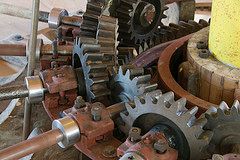
I'm planning to build a kids traditional roundabout with galloping horses.
The horses go up and down via an overhead crank, that is turned by a large fixed crownwheel and several pinions.
Like in this picture:
The problem I'm trying to overcome is, when you take down and set up this ride, you have to either completely or partially remove all of this,
even if the ride is a folding trailer mounted type.
Because of it being fixed shafts and gears.
So, my idea is to replace the centre crownwheel with a hydraulic pump, and then fit a small hydraulic motor to the end of each crank.
So it still does the same job, but there will be flexible pipes at the points where the ride folds, rather than solid shafts, making it it easier and
less complicated to take down and set up.
http://www.ppcmag.co.uk/forum/viewtopic.php?f=47&t=6743&start=105
|
|
|