FuryRebuild
|
| posted on 6/9/16 at 01:35 PM |

|
|
Metal Laser Sintering 3D Printing experience?
Does anyone have any experience of 3d metal printing, specifically around time taken and price to get a part printed?
I'm thinking mainly about printing an exhaust manifold. I can think of many advantages of doing this, but was wondering if anyone had any
experience of doing it, and what were the charges for whatever you had done?
Thanks
Mark
When all you have is a hammer, everything around you is a nail.
www.furyrebuild.co.uk
|
|
|
|
|
peter030371
|
| posted on 6/9/16 at 03:34 PM |
|
|
What are the advantages?
|
|
|
FuryRebuild
|
| posted on 6/9/16 at 03:46 PM |
|
|
from my digging around about doing a manifold, there's always a compromise between off-the-shelf components (such as collectors), packaging,
high quality bends and equal pipe lengths.
If you can print parts of the manifold, you can avoid welding (and back-purging, etc) and achieve perfectly smooth joins between pipes, as well as
having more curves.
Similarly, you can loft between the oval exhaust port and the required round port of the manifold if that's an issue. I think the duratec is
round anyway. Similarly, printing a 2->1 collector would be a smoother transition for gas than a welded one - not much, but it all adds up.
When all you have is a hammer, everything around you is a nail.
www.furyrebuild.co.uk
|
|
|
Slimy38
|
| posted on 6/9/16 at 04:27 PM |
|
|
I know very little about plastic printing, and even less about metal sintering, but I am keeping an eye on responses just to see what comes out.
One question though, why? The only printed exhaust part that I know about is on the new Koenigsegg, where money is literally no object. To stick
thousands of pounds worth of immaculate manifold on to a stinky old Duratec engine just seems a bit 'brave'.
I am fascinated to see if you get any valid responses, so please don't let my negativity put you off.
|
|
|
FuryRebuild
|
| posted on 6/9/16 at 04:39 PM |
|
|
Hi Slimy
I took this as a tongue-in-cheek response, so don't worry. I've done a bit of plastic 3d printing, so I've got my head into how this
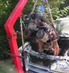
works. My duratec isn't stinky though. It's had 000s spent on it, and should rev to 9k and 230 BHP, with strength left for a super-charger
if I need one.
If you look at 2-> collector design say this one,
they're not too smooth. If you were to design that in cad and print it, you could make it more smooth, and get nice curves where it needs to
flare out after the merge.
I've looked into pricing for a top-end exhaust for mine, and it's a couple of k, so I think this route is one to explore.
I'd sooner have the part printed than weld if I could - it would save time overall and reduce opportunities for mechanical failure.
When all you have is a hammer, everything around you is a nail.
www.furyrebuild.co.uk
|
|
|
peter030371
|
| posted on 6/9/16 at 05:07 PM |
|
|
Still not sure the advantages will make an SLS part worth it (unless you have a six or seven figure car and money is no object). I have used 3trpd to
do plastic parts for work before and seen around there place many years ago before they added metal to the materials they could work with. If its
practical then I am sure they can do it, have a look here for more info http://www.3trpd.co.uk/ They have some
interesting case studies on the website.
3TRPD work with F1 teams and have done so for years....if its of any benefit over a well made tubular manifold then wouldn't' the F1 guys
use them in this application?
|
|
|
Pat_T
|
| posted on 6/9/16 at 06:24 PM |
|
|
I design engines for an OEM and we sinter a number of parts.
I wouldn't want to sinter an exhaust manifold as the sinterings tend to be quite brittle and I don't think it would deal well with thermal
expansion or thermal shock (puddle splash etc)
I would bet you'll end up with it cracking..
|
|
|
FuryRebuild
|
| posted on 6/9/16 at 07:14 PM |
|
|
Pat - that's an interesting point of view, and not one I'd thought of around the harsh thermal environment.
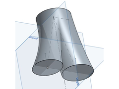
I've got a nice shape at the minute - two inlets to the collector at 45mm, and one outlet of 50mm. If I then loft and merge each inlet to the
single outlet, I get a nice organic smooth collector shape.
I'm struggling to get it hollow though, so it's not printable yet.
When all you have is a hammer, everything around you is a nail.
www.furyrebuild.co.uk
|
|
|
Bluemoon
|
| posted on 6/9/16 at 07:22 PM |
|
|
quote:
Originally posted by Pat_T
I design engines for an OEM and we sinter a number of parts.
I wouldn't want to sinter an exhaust manifold as the sinterings tend to be quite brittle and I don't think it would deal well with thermal
expansion or thermal shock (puddle splash etc)
I would bet you'll end up with it cracking..
Yep would not bother my self.. techniques like this have there place but not in this instance... also without modeling the gas flow and optimizing the
design you may not gain anything at all; not really a DIY option..
|
|
|
coyoteboy
|
| posted on 6/9/16 at 07:55 PM |
|
|
If it can be made by conventional techniques, 3D will be expensive. For example, I have a small hinge design. In singles they come in at around 450
quid. For giggles I looked at getting it printed using either sls or slm. The lowest price was 5k each, plus post-machining to fix the mating
surfaces.
And you'll be lucky to find anyone with a build volume that large.
|
|
|
bi22le
|
| posted on 6/9/16 at 09:44 PM |
|
|
quote:
Originally posted by FuryRebuild
Pat - that's an interesting point of view, and not one I'd thought of around the harsh thermal environment.
I've got a nice shape at the minute - two inlets to the collector at 45mm, and one outlet of 50mm. If I then loft and merge each inlet to the
single outlet, I get a nice organic smooth collector shape.
I'm struggling to get it hollow though, so it's not printable yet.
What are you modelling this on? ProE? Solidworks?
If you are creating a tube structure you should use a tube extrusion technique which means you should not have to hollow.
Track days ARE the best thing since sliced bread, until I get a supercharger that is!
Please read my ring story:
http://www.locostbuilders.co.uk/forum/13/viewthread.php?tid=139152&page=1
Me doing a sub 56sec lap around Brands Indy. I need a geo set up! http://www.youtube.com/watch?v=EHksfvIGB3I
|
|
|
phelpsa
|
| posted on 6/9/16 at 09:52 PM |
|
|
You'll probably be looking at £10k+ for a DMLS manifold. The machines are amazingly expensive, as are the materials they use.
|
|
|
Slimy38
|
| posted on 7/9/16 at 08:24 AM |
|
|
quote:
Originally posted by FuryRebuild
I've got a nice shape at the minute - two inlets to the collector at 45mm, and one outlet of 50mm. If I then loft and merge each inlet to the
single outlet, I get a nice organic smooth collector shape.
Ah, you've answered my other question, I was going to ask whether you had someone designing the exhaust for you. Again, my knowledge of engine
design is almost zero, but I do know there are a multitude of variables to putting together a good manifold for the torque curve you're aiming
for. Would it not be better to use some of the money to buy a designers time, who can get you a well designed exhaust using 'standard'
manufacturing techniques?
(By the way, I'm still way out of my knowledge zone with this so please read this in the same way as my previous post  ) )
|
|
|
FuryRebuild
|
| posted on 7/9/16 at 09:16 AM |
|
|
Description
So, I have an exhaust spec - I licensed the SBD one. it's already well optimised for exactly my spec of engine. What I'm thinking of now
is how to optimise around that, and if I could get merge-collectors printed at a couple of hundred pounds each, I'd seriously consider it.
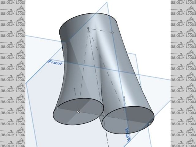
I hope the quick and dirty grab from CAD shows more what I'm trying to achieve - if you were to loft between a smaller inlet port and a larger
outlet port, and merge the two together, you get a very optimised merge collector.
Pat's point is quite valid around exhaust leaving the head. I'm going to solid-mount my engine, but that's still quite a transition
point for vibrations. Further down the exhaust I may be safer.
CAD wise, I'm using onshape.com (free to me, and does a lot of what I need whilst being easy to use)
When all you have is a hammer, everything around you is a nail.
www.furyrebuild.co.uk
|
|
|
coyoteboy
|
| posted on 7/9/16 at 11:27 AM |
|
|
You're going to get a shock if you think you can get them for a couple of hundred quid each. I urge you to submit a quote request to a supplier
with a similar model ASAP so you don't continue to waste your time.
Trust me (and others on here) - I do this as my day job!
You'll need not only to print it, and the materials available are not overly exhaust-friendly (won't weld nicely with commonly available
exhaust tubing, but you'll also need to machine interfaces so that they seal properly, and machining those interfaces will not be cheap on top
of the original cost.
I dare say you could cast an optimised one cheaper than 3D print it.
|
|
|
peter030371
|
| posted on 7/9/16 at 11:42 AM |
|
|
quote:
Originally posted by FuryRebuild
..... if I could get merge-collectors printed at a couple of hundred pounds each, I'd seriously consider it.
add a zero to that! A similar sized plastic part cost me £300-£400 recently and that was after shopping around, metal will cost a lot more 
|
|
|
coyoteboy
|
| posted on 7/9/16 at 01:42 PM |
|
|
I've spoken to a number of SLM/SLS machine manufacturers in my wanders. All of them say it's only going to be useful if you have deep
pockets or something that cannot be made as one item any other way (and are willing to pay for the reduction in assembly/fabrication cost).
3D printing isn't the panacea of all manufacturing ills, it's a specific (bloody expensive) tool to make things you can't make any
other way.
|
|
|
cr500dom
|
| posted on 29/9/16 at 10:56 AM |
|
|
If you use someone decent for the exhaust, they will weld and blend internally with a die grinder as they go.
One bend at a time.
Not cheap, but the best way to do it.
"Rapid Proto / 3d printing" is a hideously expensive way of doing it and the materials are not really up to dealing with exhaust gas Temps
and thermal cycles for very long either.
If you are only at 230hp with your duratec then Id say you are looking in totally the wrong area for incremental gains.
Come back to this when you are at 270+hp from a 2L
Up to that point (and beyond) a conventional manifold from Simpsons / Edwards will be more than good enough
|
|
|
WesBrooks
|
| posted on 29/9/16 at 08:46 PM |
|
|
I've a little experience with these machines. Ran SLS plastic machines, ran metals machines, and managed the development of the control system
for one of the metals machines.
While a quote wouodn't hurt people's estimates of costs here aren't unreasomable.
I've little more to add to what others have already said. Machines with build areas much larger than 250mm side cube are rare. Full height
builds are slow and there are not insidnificant challenges relating to residual stresses (you are essentially stacking up track after track of weld)
and supporting the part so that it can build. Most machines use a single laser with a spot of about 50-150 microns, and the layers themselves are
often about 30 micron thick. Breaking that down you'll have around 333 layers to complete for each 10mm of height.
If your desperate to use Additive Manufacturing in some way I'd consider using them to produce the core for an investmemt cast part, or perhaps
produce the sand cast mold directly. Whether that would outperform a welded exhaust in use I couldn't say. There would be a lot of rough surface
on the inside that you wouodn't be able to smooth. You'd likely have the same problem with a metal AM part.
Currently if you are attempting to make something that can be made relatively straightforwardly using traditional techniques the chances of Additive
manufacture being a sound choice is small. If however you have small highly detailed parts, or are looking to remake a multiple part assembly as one
then the case study begins to look far more viable.
http://doctrucker.wordpress.com
|
|
|
FuryRebuild
|
| posted on 30/9/16 at 07:48 AM |
|
|
Thanks - I've been using additive plastic to make some prototype parts for my fury. I'm using them to get a dimensionally accurate part
before cracking a mould off it. I'm finding this process far better and less messy than the old way, of making parts with foam filler, kitchen
sink, etc.
I was thinking about exhaust manufacture and for a lot of the collectors that need to step up after a 2-into-1 merge, they don't seem to be as
smooth as one can achieve by lofting and merging - they can't be.
This got me to thinking about whether it could be printed, but the advice here all stacks up that the metallurgy just isn't right.
I could see a potentially cast part would work, but was mainly interested in exploring the concept. It's been a good discussion.
When all you have is a hammer, everything around you is a nail.
www.furyrebuild.co.uk
|
|
|
WesBrooks
|
| posted on 30/9/16 at 07:56 AM |
|
|
I'll try and add a little more positive stuff over one of the next few work lunches to balance the tone out a bit. As you say there are viable
applications for AM (additive manufacture) for people who are making there own equipment.
They've used plastic extrusion AM machines to make chassis for cars after all! BAAM - from memory rather I think that's Big Area Additive
Manufacturing. It's a beast.
http://doctrucker.wordpress.com
|
|
|
WesBrooks
|
| posted on 30/9/16 at 02:36 PM |
|
|
Most of this will be pretty obvious to many on here. Designing for AM has unique differences to designing for machining or sheet metal work.
AM is great for small, low volume parts, high complexity parts or reducing an assembly of parts to a single part - such as that jet engine fuel nozzle
application. Start to push one of these criteria too far and things get very pricey very quick. The exhaust is low volume - 1 - but the shear size of
it and need for high melt point metals make it a costly - but not impossible - proposition.
Within the kit car and home builder environment I would imagine most of the applications within the engine environment would be uneconomical due to
the high mechanical or thermal loadings or shear size. Maybe fuel nozzles could be considered, but I'd expect they require a smoother surface
finish than what can be achieved on most AM machines, and there are plenty of existing ones produced in large volumes to choose from.
I could see many application within the interior and dash board though. Could get a nice factory finish look with some thought and plenty of hand
finishing! Exterior, chassis, and suspension applications would be limited too. I'd never consider it for a one off safety critical application.
Predicting how a AM part will behave mechanically is not straight forward. No one can do that yet with a high enough degree of certainty to build
something one off that your life depends on. Most applications like this in industry would have spares made that are tested to destruction. While this
probably is the same for machined parts the main concern is AM parts don't tend to behave isotropically. The mechanical properties in the x axis
is different to y and z. With metal for example a part with thin wall section will have different bulk material properties to a thick section part.
This can be balanced a bit with processing parameters but if both exisit in the same part it's a balance.
Almost random collection of general considerations for most processes:
~ Most processes work in layers. x & y axis are generally considered as the two parallel to the ground and z points to the sky! The layers are
generally stacked on top of each other in the z direction, parallel to the x/y plane. Same as most CAD systems.
~ The layer-wise AM processes take 3D CAD data and break it down to 2D layers. Generally this is information on the system for what material to
process and what not. For those familiar with CNC the layer data is often a tool path, but describing where the extruder, or energy source is
directed. Only thing is this is a negative of the CNC path. AM adds the material where needed whereas CNC cuts it away.
~ Try to avoid thick sections. For instance if you need lots of 10mm wall sections for mechanical strength then chances are AM is not the process to
use. For an exhaust header I'd probably consider a 1mm section a minimum, and try to keep the pipes straight up and down in the build volume.
You may be able to get away with less but there isn't much spare for removing supports and to resist residual thermal stresses.
~ Build time will often determined by a balance of z-height and solid volume. Minimising volume will reduce build time and cost. Build time for thin
walled parts will become dominated by height.
~ Consider you design and where you 'a-surfaces' are. These are ones that you want best accuracy or finish on. Let the people know who are
quoting what features are most important to you. They can adjust the part orientation to give best results.
~ Like when designing plastic parts avoid sudden section change. A smooth flowing section change in the z-axis will give best results.
~ With layers you get stair stepping. For aesthetic or fluid flow applications this may require significant post processing - often by hand - to
remove.
~ Powder based processes generally has a rough finish which is between a sand cast and a heavy spark finish.
~ Accuracy is generally around +/- 0.15mm for a part removed from the substrate that has not been processed before. The operator may choose to repeat
build with different scales and offsets to improve this. This wouldn't be economical for a one off. For fitting parts things often need fettling
or post machining. Higher accuracy machines (particularly with plastics) are around, but often limited to a smaller working area due to the optic
issues.
~ Supports are generally required for 'over hanging' surfaces. Overhanging surfaces are where the the solid bits of the layer are over
free space rather than previously processed material or the base substrate.
~ Some processes require supports on all over hanging surfaces. Others such as plastic SLS require little or none - but often need other tricks to
keep parts flat. With most metal and stereolithography processes if there is more than a 40 degree angle between the x/y plane and the section of
surface you are checking then some of the processes that use supports will get away with far less supporting, often only needed for a long span.
~ Supporting increases hand finishing time, but with excessively little supports some parts will distort mid build and crash the build process.
[Edited on 30/9/16 by WesBrooks]
http://doctrucker.wordpress.com
|
|
|