scudderfish
|
| posted on 16/2/23 at 02:24 PM |

|
|
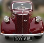
Looks like a mudguard from a lorry
|
|
|
|
|
Prof_Cook
|
| posted on 28/2/23 at 06:58 PM |
|
|
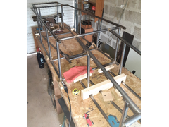
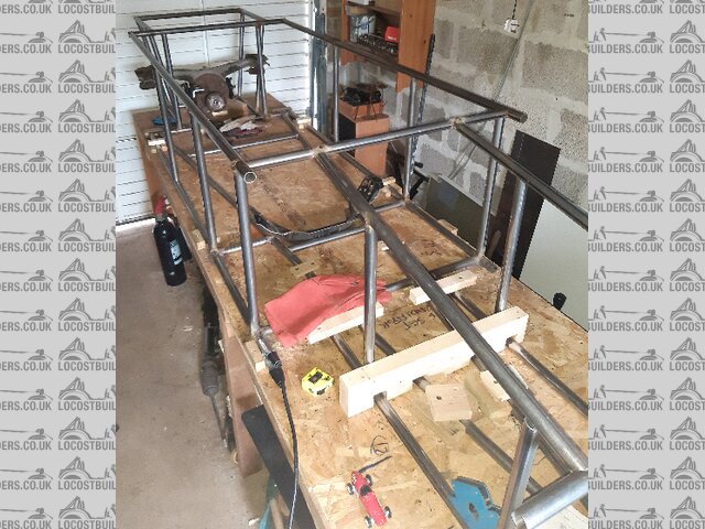
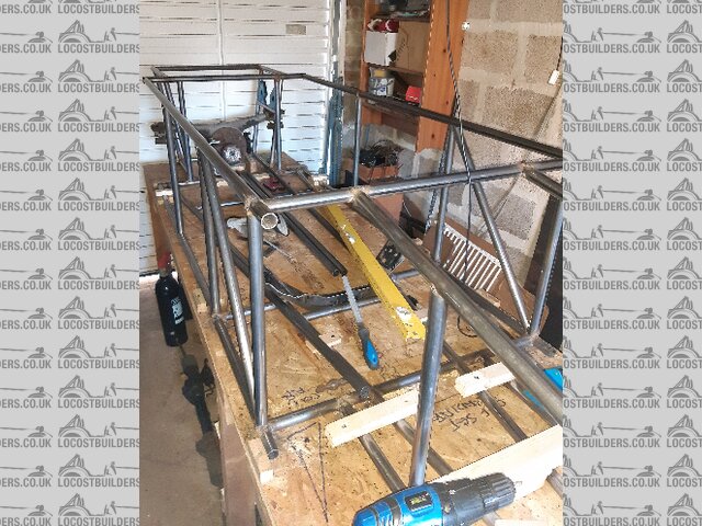
Initial frame tack welded
Progress as at end Feb 23.
Good news: Initial frame tack welded. 14 out of 16 uprights cut to length, hand fitted then tack welded. Measured and is square with tubes
perpendicular/parallel where applicable (Exception is tubes fore/aft of diff). 2 tubes remain
Initial frame
Bad news : Nothing really. Only reason last 2 uprights are still unfitted/welded is reviewing front layout design.
Plan for period up to Summer:
Fit last 2 uprights and then start the triangulation process. Will need to seam weld any hidden joints and then tack weld in the triangulation pieces
(ie on side frames, wishbone suspension location points and the top cross rail between engine bay and forward top rails).
Fit engine mounts.
Once frame is seam welded will be able to dismantle build table and transfer frame onto stands, lift engine/gearbox into frame and then fit/weld
triangulation in engine bay and start the straight and arched cross pieces which will carry the steering assembly (etc) and bodywork, and fit brackets
for engine bay components.
Fit differential and then the short PPF replacement to connect differential to gearbox. This will then determine the layout position for the seat (as
low as possible while clearing prop shaft/PPF).
Total expenditure to date is £760.
[Edited on 28/2/23 by Prof_Cook]
|
|
|
Prof_Cook
|
| posted on 8/3/23 at 04:05 PM |
|
|
Triangulation
Before cutting steel tubes for the triangulation of the side rails, I wondered what options were available for the layout of the triangulation
tubes.
A chassis can be considered as a form of bridge between two load carrying points ( the front and rear axles) and I found this piece of simple analysis
of two types of truss bridge: https://digitalcommons.murraystate.edu/cgi/viewcontent.cgi?article=1164&context=postersatthecapitol
From this paper, option B below would seem to provide the lowest compressive forces on the tubes to the side of the cockpit and hence drivers postion.
So I will go with that layout.
 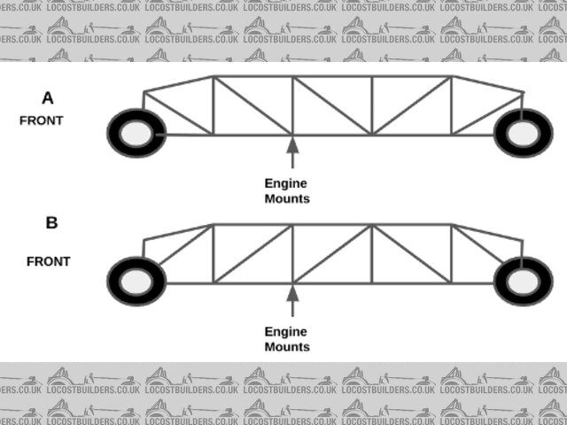
triangulation_options
[Edited on 8/3/23 by Prof_Cook]
|
|
|
Prof_Cook
|
| posted on 15/3/23 at 06:16 PM |
|
|
First triangulation in
First triangulation pieces cut to length and fitted to frame rails ready for tack welding. Off-cuts used for diff mounting rails. Magnets just for
show pending decision on diff mounting height relevant to bottom face of frame:
Triangulation_1
Total steel used to date is 31.5m (including 4 tubes still to be cut to length and installed). Calculated frame weight is 36Kg so will be interesting
to see what it weighs when removed from build table. Couple of metres of tube still to be obtained and welded on to support body work and form roll
hoop. So hoping to keep frame to about 45Kg.
[Edited on 15/3/23 by Prof_Cook]
|
|
|
Prof_Cook
|
| posted on 15/3/23 at 07:02 PM |
|
|
Revised weight budget
Donor car developed 115BHP (I thought it was 105BHP) so to get to 307BHP/Tonne of the target car my project needs to max out at 375Kg. I have been
weighing some of my components so with some still to be finished and weighed my car will be some 75Kg over budget and thus power to weight should be
256BHP/Tonne..
Engine 124.7 = 27.74%
Wheels/Tyres 55.2 = 12.28%
Hubs/Uprights 48.8 = 10.85%
Frame 45.0 = 10.01%
Gearbox 36.3 = 8.07%
Differential 28.4 = 6.32%
Fuel Tank 20? = 4.45%
Wishbones 20? = 4.45%
Bodywork 20? = 4.42%
Seat 11.3 = 2.51%
Radiator 9 = 2.00%
Steering Rack 7.9 = 1.76%
Steering Wheel/Column 6 = 1.33%
ECU and Loom 5? = 1.11%
Lights 4? = 0.89%
Battery 3? = 0.67%
Handbrake 3? = 0.67%
Dashboard 2? = 0.44%
449.6
Challenge -74.6
[Edited on 15/3/23 by Prof_Cook]
|
|
|
Mr Whippy
|
| posted on 16/3/23 at 07:22 AM |
|
|
Mind to make the passenger compartment stronger than the front or back unless you want to be sitting in the crumple zone.
|
|
|
Prof_Cook
|
| posted on 16/3/23 at 08:04 AM |
|
|
Passenger compartment crumble zone
Many thanks for the comment and Yes you are of course right and you have succintly articulated what I have been thinking of when thinking about the
triangulation. Decided to have internal triangulation in passenger compartment but actual tube layout will be done once seat positioned and control
layout fixed. Probably slanted "hoop" round from back of seat up to bottom of scuttle tied into top of frame rails.
|
|
|
pigeondave
|
| posted on 20/3/23 at 01:39 PM |
|
|
quote:
Originally posted by Prof_Cook
Before cutting steel tubes for the triangulation of the side rails, I wondered what options were available for the layout of the triangulation
tubes.
A chassis can be considered as a form of bridge between two load carrying points ( the front and rear axles) and I found this piece of simple analysis
of two types of truss bridge: https://digitalcommons.murraystate.edu/cgi/viewcontent.cgi?article=1164&context=postersatthecapitol
From this paper, option B below would seem to provide the lowest compressive forces on the tubes to the side of the cockpit and hence drivers postion.
So I will go with that layout.
triangulation_options
[Edited on 8/3/23 by Prof_Cook]
So what's the advantage of having a smaller compressive force in the members?
Have you re-sized them as they are under less load?
Which option gives the least deflection?
Also those pics are loaded differently. How does the top one behave if the load is in position 2 like the bottom pic?
It reads to me like the experiment was to identify the lowest max compression not what the compression is with both trusses loaded at the same place.
|
|
|
pigeondave
|
| posted on 20/3/23 at 01:55 PM |
|
|
If you want a few good chassis papers to read you could go to
https://locost7.info/mirror/chassis.php
Final thesis A and B are good reads. As is the kitcaranalysis doc
|
|
|
Prof_Cook
|
| posted on 20/3/23 at 07:08 PM |
|
|
Hi pigeondave many thanks for your comments and the links. Turning to your questions:
So what's the advantage of having a smaller compressive force in the members? - I assumed that having a lower compressive force in the cockpit
side members would reduce risk of collapse and thus improve the safety factor in this area.
Have you re-sized them as they are under less load? - No, kept to same size and wall thickness as the other frame members.
Which option gives the least deflection? - No knowledge.
My reading of the one page description of the experiment was that the max compression was identified for each truss design loaded at the three load
points and then the bottom design gave a max compression figure which was lower than. I also found the following "report" which chose Howe
design as having lowest stress: https://www.researchgate.net/publication/348579526_Designing_a_Truss_Bridge
I read the linked files and was intrigued in one of the papers at the description of a "ring beam" in the open top of the engine bay to
provide a degree of triangulation. I was looking at a "Y" brace from the rear of the engine bay/base of scuttle down to the front corners of
the engine bay with the "Y" brace being bolted into position (to allow engine removal/installation). So I will now be considering a
"ring beam" for the engine bay. That design choice will be made once the main frame is seam welded up and the engine/gearbox assembly loaded
into it so I can see exactly how much space is available between top frame rails and intake/exhaust manifolds.
[Edited on 20/3/23 by Prof_Cook]
|
|
|
coyoteboy
|
| posted on 21/3/23 at 11:23 AM |
|
|
Don't forget torsional stiffness of the chassis, or it will twist like mad in a corner.
While not the same type of car, and a different chassis style,
this might be an interesting read for you.
Unless you're working from a book design of chassis, you should really design the chassis last.
[Edited on 21/3/23 by coyoteboy]
|
|
|
Prof_Cook
|
| posted on 21/3/23 at 05:31 PM |
|
|
coyoteboy many thanks for your comments and the linked analysis file. Yes I did previously read it and changed the design of the lower rails of the
frame to incorporate triangulation. As you correctly stated, torsional stiffness is a key element of handling and once the initial frame is seam
welded up and on stands, I will then mount the engine/gearbox and other major components to their mounting brackets and then see what opportunities
are available to incorporate transverse triangulation.
In an ideal world I would CAD the design and then spend months optimising the tube layout, but (1) I don't have the funds for that software and
(2) I have noticed on various forums that a proportion of projects fall by the wayside due to design inertia.
|
|
|
coyoteboy
|
| posted on 21/3/23 at 05:47 PM |
|
|
quote:
Originally posted by Prof_Cook
In an ideal world I would CAD the design and then spend months optimising the tube layout, but (1) I don't have the funds for that software and
(2) I have noticed on various forums that a proportion of projects fall by the wayside due to design inertia.
That's very true, its always a balance of optimisation vs just getting on with it and seeing. I'm a big fan of seeing the chassis as a
bracket though, and all your loads going in through nodes, which the "just build it" route tends to ignore. Hopefully a halfway house is
achievable! 😊 Keep up the good work.
|
|
|
Prof_Cook
|
| posted on 21/3/23 at 07:47 PM |
|
|
£809 spent
£461 for components (steel tubes). final tubes for main frame purchased and delivered today. Now to cut, fit and tack weld them in.
£348 for books and tools.
|
|
|
Prof_Cook
|
| posted on 6/4/23 at 06:35 PM |
|
|
No more money spent.
Work continues on cutting, filing and fitting tubes for tack welding.
Continue to find components (mostly plastic ties for the wiring loom) and some tools (a knife this month) when out walking the dogs:
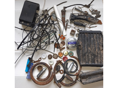 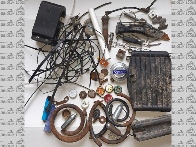
March_finds
A few pennies for the build kitty. The number of laughing gas cylinders is very few.
|
|
|
Mr Whippy
|
| posted on 7/4/23 at 06:31 AM |
|
|
quote:
Originally posted by Prof_Cook
coyoteboy many thanks for your comments and the linked analysis file. Yes I did previously read it and changed the design of the lower rails of the
frame to incorporate triangulation. As you correctly stated, torsional stiffness is a key element of handling and once the initial frame is seam
welded up and on stands, I will then mount the engine/gearbox and other major components to their mounting brackets and then see what opportunities
are available to incorporate transverse triangulation.
In an ideal world I would CAD the design and then spend months optimising the tube layout, but (1) I don't have the funds for that software and
(2) I have noticed on various forums that a proportion of projects fall by the wayside due to design inertia.
As I've mentioned before, one good way to test a chassis is to build a scale wooden model, balsa being ideal. It will cost very little and only
take a couple of evenings but then you have a chassis you can twist and flex in your hand, then improve or test ideas on. I've built lots of
model planes with such spaceframe structures and nothing beats having something in your hands to feel just how strong they are.
|
|
|
Prof_Cook
|
| posted on 23/4/23 at 08:19 PM |
|
|
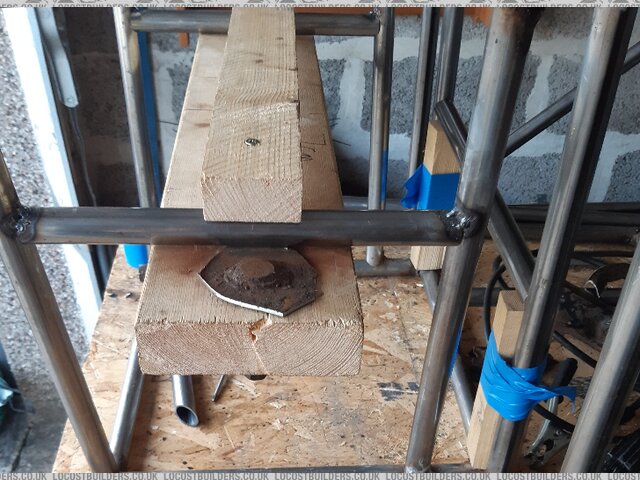
Many thanks for the comments and agree as did 3 balsa models. Now using "full size" wood to confirm tube layouts. Been laid up this month,
but when back up and around I found a nice clean unstained/unpainted "HT = Heat Treated" pallet which has been broken up and is being used
for pizza oven fuel and for full frame modelling to confirm main tube layouts and confirm construction sequence.
 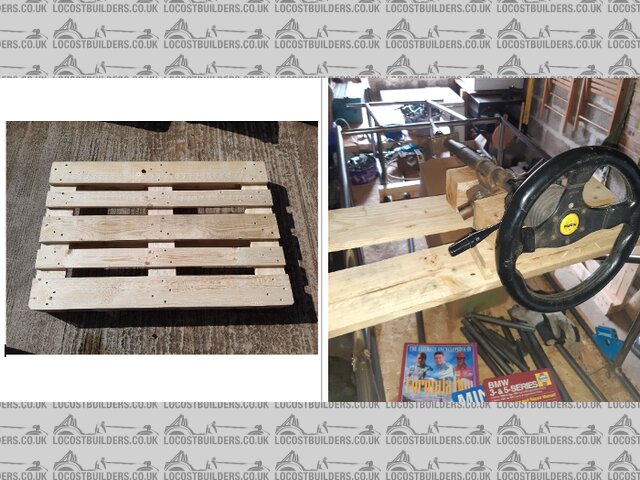
Pallet_Use
Now this has confirmed that will need to have steering column carried on bolted in cross members as steering column runs above rear of engine and to
allow engine to clear into the engine bay I will need to fit steering column and intermediate steering shaft above engine after engine
installation.
Weighed the battery today, 11Kg. A bit heavier than my original estimate of 3Kg! So my progress on the weight challenge is going the "wrong"
way. Cheapest option would be to dispense with electric start, fit small motorcycle battery and also save the starter weight and use rope starting as
there is now a "spare" pulley on the front of the crankshaft as I ditched the Power Steering and Air Conditioning:
https://www.youtube.com/watch?v=_0naTvrigBY&ab_channel=ShaketheFuture
Dont think "pull starting" would work on a MX-5 engine: https://www.youtube.com/watch?v=HyiQ_bHkDts&ab_channel=B%C3%B8mloBricks
Options to consider once the car is finished and on the road as suspect IVA examiner would be surprised at such novel ways of starting the car...
Other finds this month were an Encyclopaedia of F1 racing and Haynes manuals for Mini and BMW cars.
To create the above image of 2 photos alongside each other. The 2 original photos were sent by e-mail from my phone to my chromebook. Then opened
google docs, created a blank document, then inserted a table of 2 columns. Then inserted a photo into each cell. Took a screenshot and then opened the
screenshot, cropped it and then saved as a .jpg then uploaded to the site after reducing the scale using the rescale function.
[Edited on 23/4/23 by Prof_Cook]
|
|
|
Mr Whippy
|
| posted on 24/4/23 at 11:49 AM |
|
|
There's nothing wrong with a handle to start it up...
|
|
|
Prof_Cook
|
| posted on 25/4/23 at 07:42 PM |
|
|
Many thanks Mr Whippy for your comment. Yes I had thought about a starting handle as another option - appeals to me as pictures of the original
"target" car appear to show what could be an insertion point for a starter (handle or hand held electric motor?) in the air intake. Problem
is with my car is that the "stock" MX5 radiator being reused sits right in front of the engine and to get a starting handle onto the
crankshaft pulley would require me making a 25-30cm diameter hole in the lower middle of the radiator matrix - I don't think my fabrication
skills would be up to making such a hole in the radiator water tight!. Also I have no knowledge if the MX5 Mk1 engine could be started using a
starting handle...
Resigned to keeping current battery and starter motor until car mobile then will investigate the art of the possible.
[Edited on 25/4/23 by Prof_Cook]
|
|
|
Prof_Cook
|
| posted on 25/6/23 at 11:43 AM |
|
|
£858
Total expenditure to date, including latest steels and sundries delivered into workshop. Been out of workshop for last 6 weeks, but now back in.
Next few weeks is for practicing arc welding on off-cuts to improve my welding before seam welding basic (triangulated) frame.
|
|
|
Slimy38
|
| posted on 25/6/23 at 02:14 PM |
|
|
A few extras for the weight list, although I'm not sure whether they apply for you;
Propshaft/driveshafts.
Brakes discs/pads/calipers.
Pedal box (with cylinders).
Have you included the roll cage as part of the chassis? I bought mine very recently from 'the tube bender' on Ebay, I can recommend their
services if you want something you can trust should the worst happen. Again it's more weight though, I'd say my roll cage is about 15
kgs?
It's also interesting that you're reusing many of the parts. For example my car is a Seven base but with a Healey body on it, and I still
couldn't get the MX5 radiator to fit. You've got even less than me, so I'm impressed you've managed to get it to fit. I am reusing
one of the fans though.
Oh, and I will have to pinch your idea of cutting down a plastic barrel for wheel arches!! I have to put together some flared arches for my car
(slight failure in design), and I couldn't figure out how to do it. A plastic barrel makes a lot of sense.
|
|
|
Prof_Cook
|
| posted on 18/7/23 at 12:57 PM |
|
|
Another Free Component
Update:
Bad News : Progress not as fast as planned. Hand filing the ends of the triangulation tubes is taking longer than I thought it would!
Good News:
1. Frame construction continues.
2. No money spent since last update.
3. Sheet steel found at side of road will be converted into either firewall between engine and drivers compartment or perhaps cut up and used for
floor either side of transmission tunnel. The sheet steel was a "fire cowling":
 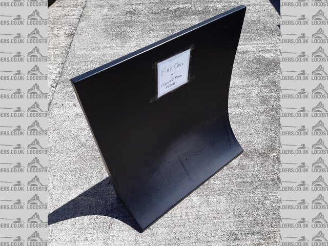
Free Sheet Steel
|
|
|
Prof_Cook
|
| posted on 18/7/23 at 01:02 PM |
|
|
quote:
Originally posted by Slimy38
A few extras for the weight list, although I'm not sure whether they apply for you;
Propshaft/driveshafts.
Brakes discs/pads/calipers.
Pedal box (with cylinders).
Good points Slimy38.
No - hadn't considered the propshaft and driveshafts.
Yes - brake discs/pads/calipers within weights shown.
No - handn't considered the pedal box with cylinders.
Will revisit weight spreadsheet over next few weeks.
Many thanks
|
|
|
Prof_Cook
|
| posted on 31/8/23 at 09:35 PM |
|
|
Differential
Good news:
Triangulation side pieces finished and tack welded in. (Now cutting/shaping main cross triangulation pieces at front of engine and triangulation
pieces at rear/side of drivers position to ensure it is not the crumple zone).
Differential mounting position finalized - longitudinal carriers tack welded in and present the 2.2 degree tilt to the differential mounts which will
comprise of original differential mounts re-used. Vertical position should result in half-shafts being horizontal when car sitting on its wheels...
Bad News:
No real bad news (except for not getting enough time in the garage),
Total spend now £870 (more welding wire).
|
|
|
Prof_Cook
|
| posted on 6/9/23 at 08:48 PM |
|
|
Diff bolts cut out of old sub-frame and jigged up to longitudinal carriers:
Diff bolts in jig
|
|
|