geoffe
|
 posted on 18/4/06 at 07:33 PM posted on 18/4/06 at 07:33 PM |

|
|
LED Rear Indicators
It's daft questions day today!
I've got a pair of SVC LED rear indicators; very smart. I've also got resistors to fit.
Where abouts in the circuit do they go? and are they in series or parallel?
I'm only a simple sailor so help would be appreciated.
Thanks,
Geoff.
|
|
|
|
|
piddy
|
| posted on 18/4/06 at 07:39 PM |
|
|
Hi.
One lead to earth.
the other to the indicator feed.
|
|
|
JohnN
|
| posted on 18/4/06 at 08:02 PM |
|
|
Resistors need to go in series with each indicator light. They need to dissipate approx. 20 watts for indicators, so can get hot, bear this in mind
when locating them.
If I remember right, I got some fancy alloy heatshielded resistors from SVC, which didn't work, in the end I just substituted some simple 5 or
so Ohm, 20+ watt, ceramic resistors from Maplin for a few pence each. Indicators now work a treat.
[Edited on 18/4/06 by JohnN]
|
|
|
RazMan
|
| posted on 18/4/06 at 08:15 PM |
|
|
quote:
Originally posted by JohnN
Resistors need to go in series with each light. They need to dissipate approx. 20 watts for a brake light, so can get hot, bear this in mind when
locating them.
Sorry but that is wrong - the resistors are in parallel. Their function is to create a dummy resistance (and therefore current flow) Led's
consume very little power so the conventional flasher unit will not function properly.
Better still, why not do away with the resistors (they create a lot of unneccessary heat anyway) and change the other indicators to led versions, then
swap the flasher unit for an electronic flasher - much less power consumption.
You can change the bulbs for units like these....
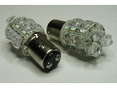 
Rescued attachment 1157_flux.jpg
Cheers,
Raz
When thinking outside the box doesn't work any more, it's time to build a new box
|
|
|
k33ts
|
| posted on 18/4/06 at 08:56 PM |
|
|
as piddy stated
one end to earth other end to indicator supply
obviously one for each side
tukcustoms.com
|
|
|
JohnN
|
| posted on 18/4/06 at 10:14 PM |
|
|
Well spotted, RazMan, I was of course talking complete bo£$%cks........ I'll get my coat.
|
|
|
nitram38
|
| posted on 19/4/06 at 03:25 AM |
|
|
Sorry to contradict your statement razman, but if you put a resister in parrallel, then there will still be 12v supplied to the leds, so the current
flowing through will still be the same? The only device to alter current in parrallel, is an ultra low resistance such as a direct link of copper
(normally called a shunt but only used on ammeters).
When you put a resister in series, you reduce the voltage across the led and therefore the current flowing through them.

|
|
|
matt_claydon
|
| posted on 19/4/06 at 08:12 AM |
|
|
quote:
Originally posted by nitram38
Sorry to contradict your statement razman, but if you put a resister in parrallel, then there will still be 12v supplied to the leds, so the current
flowing through will still be the same? The only device to alter current in parrallel, is an ultra low resistance such as a direct link of copper
(normally called a shunt but only used on ammeters).
When you put a resister in series, you reduce the voltage across the led and therefore the current flowing through them.
I believe in this case the resistor is not there to limit the current through the LEDs, but to make the resistance (and hence current flow) of the
unit as a whole the same as a standard bulb, such that a normal flasher unit will work.
|
|
|
nitram38
|
| posted on 19/4/06 at 02:09 PM |
|
|
That makes more sense.
If the led has a low resistance then the flasher will go faster ('hotwire' flasher, not electronic type).
Putting the resister in parallel will mimic a greater load and therefore allow the flasher to run at the correct speed.
|
|
|