ever88
|
| posted on 21/7/07 at 02:31 PM |

|
|
is this dimension correct from the book
hi all
I wonder if many of you come across this possible dimension error in the build your sports car locost book
I building the front end at moment and looking to position front suspension mounting brackets as per page 63 BUT
the dimension between the centres of wisbone works out to be 185mm.
as I have a set of cortina uprights with wishbones fitted, if I hold both wisbones parallel to each other I roughly measure more like 245 mm. setting
them up as per the book would have the wisbones angled in toward each other.
what am I doing wrong?
checked measurements many times and still puzzled.
any help is greatly appreciated.
cheers
|
|
|
|
|
ever88
|
| posted on 21/7/07 at 03:24 PM |
|
|
just a follow up
does anyone have a drawing they are willing to share with regards the dimensional location of the wishbone mounting positions please?
there is a lots of threads on what setup works best etc etc but not many threads with actual layout details with figures of what castor camber this
would give.
I'm using a set of ron champion wishbones with cortina uprights if this helps.
thanks to all who can help here
|
|
|
ecosse
|
| posted on 21/7/07 at 04:56 PM |
|
|
AFAIK the detail and measurements in the book should be correct for the wishbone mount locations.
Although I'm not entirely sure what it is you are asking here, have you still to weld on the wishbone brackets, or have you done this and the
measurement is wrong?
Can you explain further?
Cheers
Alex
|
|
|
Mansfield
|
| posted on 21/7/07 at 05:54 PM |
|
|
The wishbones are not designed to be parallel at normal ride height - does that change your question?
|
|
|
ever88
|
| posted on 21/7/07 at 06:04 PM |
|
|
yes thanks guys
I understand that because the wishbones are different in length that they would scribe different arcs when moving up and down but did not expect the
wishbones to be angled as severe as that.
I'm wrapping up at workshop now and will post a pic of where I thnks the brackets for the wishbones should be located and you could possibly
check my understanding if you catch my meaning.
cheers
|
|
|
RoadkillUK
|
| posted on 21/7/07 at 11:35 PM |
|
|
Would a pic help at all?
Plenty more on my website (might even update it one day)

Roadkill - Lee
www.bradford7.co.uk
Latest Picture (14 Sept 2014)
|
|
|
907
|
| posted on 22/7/07 at 06:26 AM |
|
|
First of all sorry for pinching your pic Lee.
I hope this helps.
When I positioned my brackets I used lengths of M12 studding so that I could get the two sides parallel to each other.
To miss the upright chassis member I used a spare bracket for the bottom one as in the sketch at the bottom of the pic.
I used nuts to position the brackets to match the wishbone ends.
Clamp both sides in position and measure between the two to get them parallel to each other and to the base of the chassis. (blue lines)
Do the same with the top brackets using nuts & studding and clamp into place. (green lines)
You can then measure and "eye up" the 4 studs and check that all 4 run parallel to the chassis centre line and each other.
The error in the book is that the bottom bone needs to be forward more and the top one needs to be back to give more caster.
Mine now has 22mm at the ball joints, (thanks to Mark).
Tack weld with tiny welds.
I'll post another pic after this one.
Paul G
 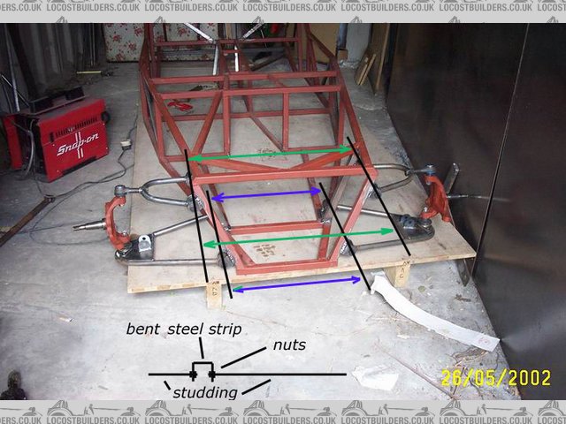
Rescued attachment locost0073-s.jpg
|
|
|
907
|
| posted on 22/7/07 at 06:33 AM |
|
|
With the studs removed, trial fit the bones & uprights.
Viewed from above you should have sufficient caster to give a degree of self centering.
Paul G
 
Rescued attachment Wishbones-s-22.jpg
|
|
|
907
|
| posted on 22/7/07 at 06:50 AM |
|
|
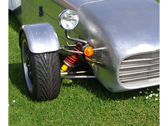
My bottom bone is parallel to the ground and the top one points up slightly.
I had to reposition my rack to get the track rods to run parallel,
and remake my w/b's because the book doesn't have enough caster. (book = 8mm)
Finished suspension should look like this.
Others have made jigs, but I found this method reasonably simple.
Tack only for the shock mounts till your engine is fitted, and beware the dreaded 1/2" shock holes if you have them.
ATB
Paul G
Rescued attachment Update-31-6-07-002-s.jpg
|
|
|
Mark Allanson
|
| posted on 22/7/07 at 11:07 AM |
|
|
like this
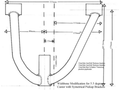 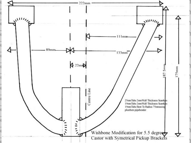
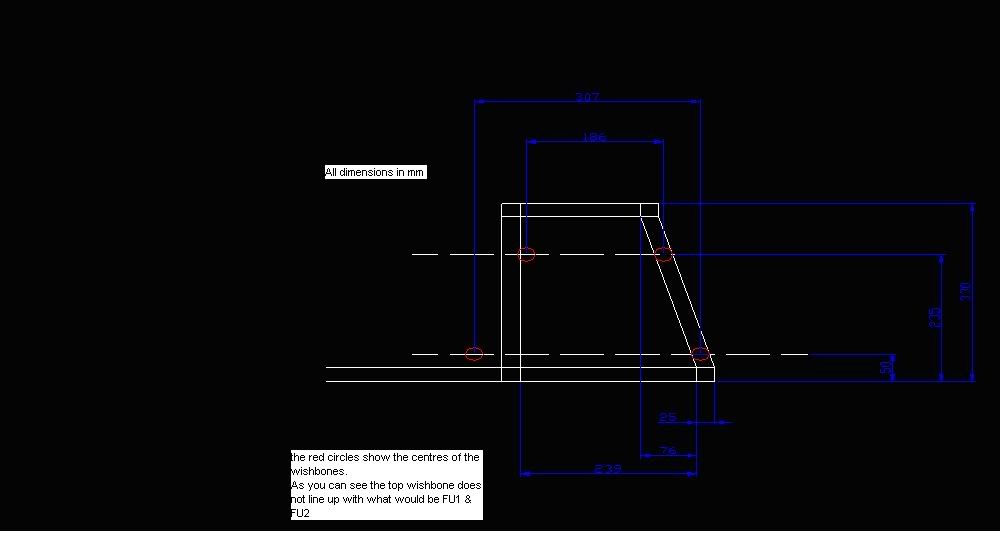
Rescued attachment Wisbone Modification.JPG
If you can keep you head, whilst all others around you are losing theirs, you are not fully aware of the situation
|
|
|
Mark Allanson
|
| posted on 22/7/07 at 11:29 AM |
|
|
how the jig works
Rescued attachment Wishbone Jig.gif
If you can keep you head, whilst all others around you are losing theirs, you are not fully aware of the situation
|
|
|
ever88
|
| posted on 22/7/07 at 11:33 PM |
|
|
many many thanks for your input here guys.
spent some time Cading this up as my chassis is different to the book as it's not a true locost I'm building but I do wish to keep the
suspension geometry to be sure it behaves correctly and doesn't crab up the road etc.
my concern is welding the wishbone mounts in the wrong place and having drawn the details from the book in Cd then used cad to insert locations of
wishbone postions I think something is wrong somewhere. I've spent so long looking at this now I have figures coming out of everywhere and
wonder if I just can't see wood for the trees.
please look at my drawing and see what you think if you have the time. you will see that the side profile of the locost chassis with front being to
the right does not allow the rear upper wishbone mount to locate where it should.

[Edited on 22/7/07 by ever88]
|
|
|