andyd
|
| posted on 18/3/08 at 03:19 PM |

|
|
Modelling a windscreen in 3D
Wasn't sure where to post this so put it in here... it's kind of related. 
My question is...
Is there anyone that has experience of modelling a compound curve windscreen using a 3D package like SolidWorks?
I don't use SW as my primary tool as it has far too many bells/whistles that just get in my way so I use Pro/Desktop 2001 which in essence works
the same way (I think).
Basically you have a workplane which can have many sketches on. The workplane can then have an extrusion or profile applied to get the 3D object. So
for a cube you'd draw a square of x y dimensions then extrude it above the workplane by a certain amount.
My problem is I'm not sure how to go about getting to a 3D windscreen using sketches. My initial idea was to create a number of cross section
sketches, extrude each to join to its neighbour and then "hollow out" to get the correct screen thickness but that strikes me as one hell
of a lot of work given quite a curved screen i.e. a Lotus Elise. I'd have to create quite a few sketches to model the subtle curve across the
width of the car. 
Anyone done anything similar before that may be able to help?
Andy

|
|
|
|
|
Neill117
|
| posted on 18/3/08 at 04:09 PM |
|
|
I have just started to work in catia so not your program and i am very new to it but my gut feeling is that i would use surfaces to generate the
shape. I would extrude one curve in the ZX along a guide curve on the XY.
This would create a rough shape that is oversize and i would use a second surface on the ZY plane to use as a cutter. The final process would be to
thicken the part.
What you describe is what catia would call a multi section solid. I think this would work but be very hard to get right and take alot of time. as it
would need very accurate guide curves and section placement.
If you dont have surfaces maybe a revolve comand based on the centre radius of the screen and then a projected cutter to create the basic shape. Then
delete the un needed faces and extrude the face that you do want.
Hope that makes sence and i'm not sure how it translates to your programme and like i say i am a little new to it but its what i would try to
see if it worked.
|
|
|
iank
|
| posted on 18/3/08 at 04:20 PM |
|
|
I have the notion from somewhere that all windscreens can be cut from a large glass cylinder (at least conceptually if not actually in practice).
Can't find an obvious reference on the web so that might be correct, old and no longer relevant or just something the voices told me.
If true it might help with the 3d CAD construction if you can work out the diameter of the cylinder somehow.
--
Never argue with an idiot. They drag you down to their level, then beat you with experience.
Anonymous
|
|
|
andyd
|
| posted on 18/3/08 at 04:25 PM |
|
|
Neil, I get where you're coming from... in Pro/D I'd have to "sweep a profile" but that may be easier than the way I was
headed. Thanks.
Ian, I think that's what Neil was referring to and in theory it sounds good.
Just need to get my head around it now and put it into practice 
Cheers guys.
Andy
|
|
|
twybrow
|
| posted on 18/3/08 at 05:31 PM |
|
|
A blended sweep I think it is called in ProE 2001. We have moved to Wildfire now, whixh once you get the basics sorted is so much simpler to use. i
never managed a blended sweep in 2001, but have done a couple in Wildfire. There will be plenty of advice out there on how to do them. Try the ProE
tutorial page....
|
|
|
Griffo
|
| posted on 18/3/08 at 05:34 PM |
|
|
this may not be too helpful and i appologise if its not but I would tend to do what you were talking about using the loft tool in solidworks.
That is how i went about constructing a solar car body I am currently designing for an assignment. whist that sounds very different from a windscreen
but is actually very similar in that it is a constantly changing curve.
|
|
|
watsonpj
|
| posted on 18/3/08 at 07:29 PM |
|
|
It depends how accurate you wish to be. In ProE for example you could use a sweep (loft in solidworks) or a variable section sweep or if you have a
screen and want to take multiple measurements in lines you can use a Boundary blended surface by defining lots of x sections in the 2 directions. You
then can use thicken to thicken it to a solid.
like this
 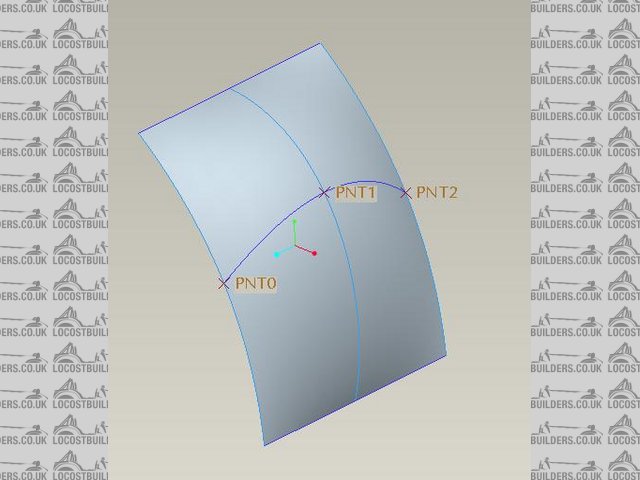
proe_blend
Its upto you how accurate you want to be but you don't need to do lots of sections if you are just after a model to use for creating bodywork as
long as you define the edges well and maybe 2-3 sections across/up
|
|
|
Jimbob
|
| posted on 18/3/08 at 07:39 PM |
|
|
I would create a profile sketch for the top of the screen on one plane, another for the bottom profile on a reference geometry plane in the correct
position(assuming the top and bottom are parallel to say x ie dont curl up at the edges or 3d sketches req) insert some guide curves at say each end
and the middle between the top and bottom profile sketches and use these for a loft feature. I will have to try it at work but im pretty sure that
would work
James
|
|
|
kastrato
|
| posted on 18/3/08 at 07:43 PM |
|
|
why you dont use 3d studio max?
much easier to model curves
you can make a plane and then bend it as much as you want then import this as dwg and you have the drawinds, sections, elvations and plans all in
technical drawing form.
That what I am using for making curve glass into buildings (I am doing an architectural postgraduate course) but I am sure that you can easily built
the whole elise in max pretty effordless.
Just foollow the tutorials easily found online
[Edited on 18/3/08 by kastrato]
MK INDY fireblade
|
|
|
watsonpj
|
| posted on 18/3/08 at 10:19 PM |
|
|
I created the example with 6 simple 2d curve created on planes in a very simple way just like Jimbob described. This is extremely easy to do and the
curve can be as simple or complex as you like and can be edited ( I used simple splines).
|
|
|
andyd
|
| posted on 18/3/08 at 10:22 PM |
|
|
quote:
Originally posted by watsonpj
I created the example with 6 simple 2d curve created on planes in a very simple way just like Jimbob described. This is extremely easy to do and the
curve can be as simple or complex as you like and can be edited ( I used simple splines).
Any chance you could let me have the file of that so i can see how you did it?
Andy
|
|
|
watsonpj
|
| posted on 18/3/08 at 11:16 PM |
|
|
I didn't save t6he oroginal but I'll do you another it only takes a couple of minutes. U2U me your email address and I'll send it
over
|
|
|
andyd
|
| posted on 19/3/08 at 05:01 PM |
|
|
Have U2U'd you.
Andy
|
|
|
dzine
|
| posted on 4/4/08 at 03:24 PM |
|
|
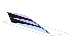
Enzo windscreen
This is what I have done recently in Autodesk Inventor, just to see whether I could.
There are a few good tutorials around about designing from 'blueprint' images. They are mostly geared at 3DS, but the principles apply to
most programs with XYZ coordinates.
Rescued attachment Enzo.jpg
|
|
|
andyd
|
| posted on 4/4/08 at 08:09 PM |
|
|
dzine... yep seen that done and will be having a bash at that when I come to design the bodywork.
As it happens I came across the "loft profile" tool in Pro/DESKTOP the other day! Didn't realise it existed and isn't a toolbar
button but just a menu option so I'd never noticed it before. So...
I drew three sketches on three spaced workplanes...
 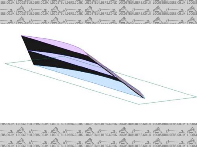
Windscreen sketches
Then lofted it and shelled it to 3mm thickness...
 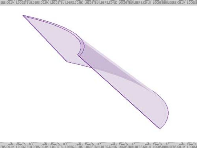
Windscreen shell
Luvvly
Now I just need the dimensions of an Elise screen to.. ahem.. "borrow" 
Many thanks to all you guys who gave advice etc.
Andy
|
|
|
dzine
|
| posted on 4/4/08 at 09:49 PM |
|
|
Yes, nice work, and looks like you found it quite easy too.
I dont want to burst the bubble, but you may find that the Elise/Exige windscreen does not have a perfectly straight side edge like you have drawn.
This is where it gets hard to model, as you need to use 'rails' within the loft feature to guide the surface out into these curves too.
I guess it all depends on what you want it for. If you are 5/6 axis milling your plug, then it needs to be accurate, but if you just want the general
look, then you are right on the money.
|
|
|
andyd
|
| posted on 4/4/08 at 10:06 PM |
|
|
Well to start with I just need a model to design the chassis around to give it the correct dimensions but at some point I'll want to actually
make up a windscreen support/roll bar which will need to allow a real screen to be fitted.
Not 100% sure I'll settle on the Lotus glass yet but as my aim is to pretty much build my own Elise I figure it's as good a place to start
as any.
Andy
|
|
|