Rorty
|
| posted on 7/1/03 at 04:05 AM |

|
|
Concern over front suspension.
I was given a book token for Christmas, and to better understand what the Locost builders here are constructing, I ordered a copy of the BYOSC book
(second edition), which arrived today.
Now I've only skipped through it over a cup of coffee, and I'm already beginning to understand some of the problems and misgivings a few of the
members here have voiced.
I want to say straight away, that I do not want to step on any toes, or dishearten anyone already building a Locost. I have built quite a few cars
over the years from scratch, learning along the way, so I have a certain quantity of experience.
I have a few queries I would like help with. I hadn't realised to what extent the front suspension brackets are "floating". That is to say, they
aren't on a single plane, nor given a "hard" location. The surfaces of the chassis that the wishbone brackets are welded to are not on the same
plane, yet they must provide comon axis for the wishbones.
I don't have a problem with constructing that (I would make a series of accurate jigs), but I would never design a scenario like that for a DIY car
that novices would be building.
The book suggests bolting the brackets to a wishbone, offering the assembly up to the chassis, while keeping the axis parallel to the centreline of
the chassis!
IMO, that's virtually impossible to do accurately.
If the method described in the book for making jigs is the method most people have used to make theirs, then there isn't a hope in hell of the axis
of the wishbones being correct in the first place.
I appreciate the use of metalastic bushes is recommended, as they will tolerate a fair amount of misalignment, but rubber bushes are designed as shock
isolators which can deflect, not rotate. If true rotation is required, then some form of bearing (plastic or metal) is needed.
But if you fit needle roller bearings or use PU bushes, then they won't work at all because of the misalignment of the sleeves on the ends of the
(book) wishbones.
If you were asked to pass a length of 8mm silver steel rod through the top two brackets for example, how many of you could do it without resorting to
heavy hammer blows?
If said rod was indeed inserted through the brackets, would it then lie parallel with the base of the chassis (asuming there is no anti dive)? What
about the axis of the bottom wishbone brackets too?
Has anyone who has finished their locost experienced suspension bind, and to what degree?
How dificult did you find the construction of the front end?
Would you prefer an easier way to do it?
Another area that worries me is the actual suspension brackets themselves. They are perched on the chassis with quite a bit of overhang on the
1"/25mm tube. With the "legs" of the brackets being unsupported, they will flex.
Has anyone with a few miles up in their Locost noticed any fractures around the wishbone brackets?
The book suggests tacking the entire suspension initially (I usually tack the entire car together before buzzing all the joints), and checking the
castor and camber before welding solid. What about checking for a square footprint? Even when I build a buggy in a jig, I always drop a plumb line
from datum points on the suspension to the floor (with caster, camber, toe set at zero), to ensure the car's footprint is square.
Has anybody ever modeled the front suspension to see what it actually does, statically, dynamically and in roll etc?
I can see where all the confusion and complaints of dimensions arise from!
Is our good friend, Jim McSorely's version enough, or is there a need for further plans?
Would it be of any benefit if there were separate, accurate imperial and metric plans?
There is a lot of talk about an independant rear suspension chassis coming up in the new book. If there is, then is it safe to assume it will be as
inacurate as its predecessors?
Does everyone buy their nose cone and body work, or do you mould your own, as suggested in the book?
Which raises another possibility. With some people choosing to fit the non "standard" Pinto engine (or any other tall engine for that matter), is
there a need for a taller chassis to accomodate taller motors?
Mr McSorely offers drawings for wider and longer (taller too?) chassis. Does anyone require more width, length or other options?
Even after only a quick glimpse at the book, I feel dissapointed. Not with the concept or basic design, but more with the manner in which some
critical areas are left wanting, and little or no guidance is offered.
I'm already thinking of redrawing the chassis both in imperial and metric units. I also would like to draw up some sensible jigs for making the
wishbones, and for positioning the brackets accurately on the chassis.
Has anyone got any suggestions regarding incorporating other features such as alternative suspension components, chassis dimensions...or whatever?

Cheers, Rorty.
"Faster than a speeding Pullet".
PLEASE DON'T U2U ME IF YOU WANT A QUICK RESPONSE. TRY EMAILING ME INSTEAD!
|
|
|
|
|
ProjectLMP
|
| posted on 7/1/03 at 05:05 AM |
|
|
I am definately interested in techniques for accurately jigging suspension pickup points etc.
Home of the Astronomicalcost Mid engined LMP project
|
|
|
kingr
|
| posted on 7/1/03 at 09:43 AM |
|
|
I'd be interested. I was planning on screwing four suspension brackets to a piece of thick MDF, and then using rod to hold the suspension brackets
that are going to be used on the chassis, then clamping the piece of wood to the chassis with the suspension brackets in contact with the chassis.
I realise that what I have just typed is perhaps not the easiest thing to understand. Anyway, hopefully provided the holes in my brackets are OK, and
I can fix them to the piece of MDF square (shouldn't be too difficult, and certainly a lot easier than doing it in 3D on different angled bits of
tube). It should also tell me if I need to shim the brackets at all.
Kingr
|
|
|
fastenuff
|
| posted on 7/1/03 at 06:55 PM |
|
|
on the net there are some jig drawings for the front suspension, but even with those it seems difficult to get it all paralel. I've toying around
with the suspesion a while ( nothing definate though) also looking at the trackwidth alterations through the suspension movement.
For the suspension pick up points I.m considering the option Leitch has used, not using brackets like the locost but bolting through the chasis.
Ingmar
|
|
|
Mark Allanson
|
| posted on 7/1/03 at 07:00 PM |
|
|
Rorty,
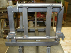
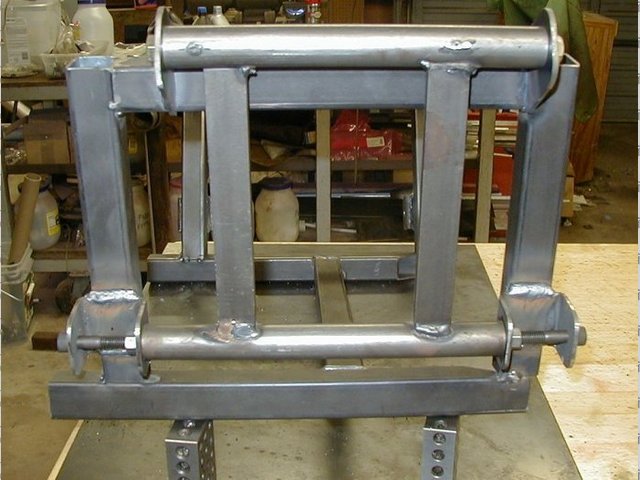
I made a jig to align the front suspension brackets, partly my own design, and partly a copy (I like the phrase 'inspired by') of something similar I
found on the net.
At work I have a Hunter 4 wheel alignment system which is computer controlled. All you do is put the sensors on the wheels and all the date is
displayed on the monitor, it measures eveything, caster camber KPI, track, thrustline, losenge. I will post a printout when I get to that stage!
A image of 'my' jig
Mark
Rescued attachment DCP_0315sml.jpg
|
|
|
Mark Allanson
|
| posted on 7/1/03 at 07:03 PM |
|
|
The jig pulled up to position, before this stage, I cut f*ck you1 and f*ck you2 out of the chassis and used the jig to set the position before welding
them in.
Rescued attachment DCP_0324sml.jpg
|
|
|
Alan B
|
| posted on 7/1/03 at 07:19 PM |
|
|
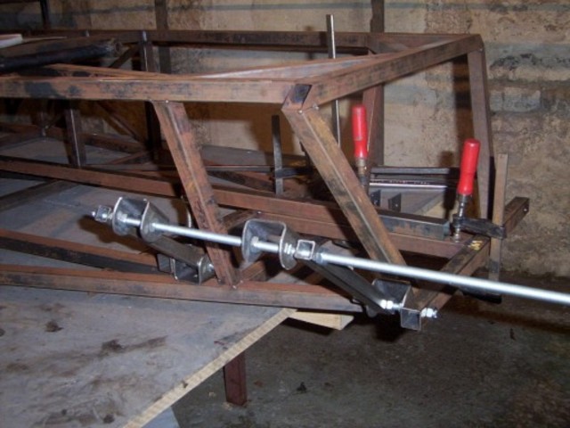
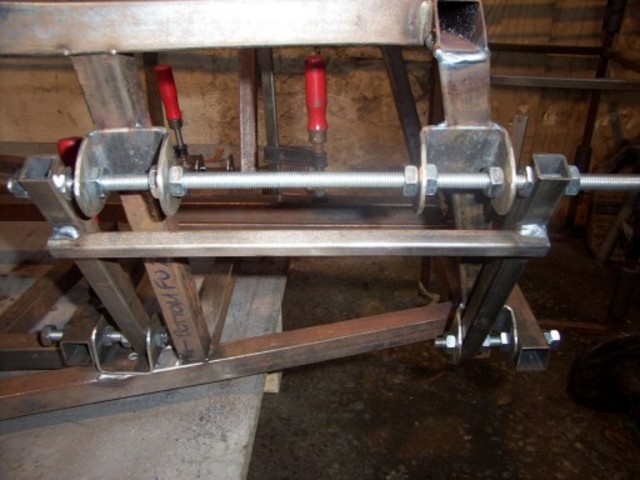
Mine is similar, but different
Same princple....locate on the holes...
suspension bracket fixture
|
|
|
RoadkillUK
|
| posted on 7/1/03 at 07:21 PM |
|
|
Merlin (wherever he is atm) made a Magic Box for the front
end.
Original Thread here
HTH
Roadkill - Lee
www.bradford7.co.uk
Latest Picture (14 Sept 2014)
|
|
|
stephen_gusterson
|
| posted on 7/1/03 at 07:25 PM |
|
|
Thing is Rorty, 1000s of people, inc those on this list, have built cars just like that!
I also reconed that the brackets are a bit wimpy. Its not just the fact they are on a 1 inch rhs - they are unbraced 3mm steel which I would like to
see even more stiffer.
On my car I ran a double section inch rhs and 50mm wide brackets, that were 'boxed' in at the sides.
As far as alignment was concerned as an amatuer I was well aware how hard it would be to get it all in line. Hence why I used adjustable everything
joints.
In my view there are a fair few bits of the car that could use extra gusseting. This is based on a lotus design after all - and lotus wer well known
for lightweight minimalist designs that killed people - Ask the first postumous world F1 champion.
atb
steve
|
|
|
geoff shep
|
| posted on 7/1/03 at 09:46 PM |
|
|
I'm glad you've said all that Rorty. I got the book for Christmas and had similar reservations, but from an inexperienced viewpoint. One thing I
didn't understand was how the suspension bushes work - surely all the suspension movement (rotation) can't be provided by the rubber. Something
must rotate somewhere musn't it?
|
|
|
johnston
|
| posted on 7/1/03 at 10:06 PM |
|
|
i remember seein somewhere pics of the trailing arm brakets fracturing so i asume the wishbone brackets would do something simiaer eventually
in regards to the bushes i was thinking of using something a bit more up to date than truimph so had a rummage round work and peugot 205gti or 405
wishbone bushes are almost the same size and i would say (but could be wrong) that a 405 would have a lot more wheel travel than a locost
|
|
|
Mark Allanson
|
| posted on 7/1/03 at 10:15 PM |
|
|
I saw the same or similar pictures, thats why I did this, you have me a little concerned about the fronts now!
Rescued attachment DCP_0274sml.jpg
|
|
|
stephen_gusterson
|
| posted on 7/1/03 at 10:47 PM |
|
|
nice bracket mark and nice alignment system too.
The rear bracket still relies on the single rhs you have welded it to. If one end cracks then the rhs will come off with your bracket!
Lets not get too worried here - if lots of people were being totalle I think Haynes would have pulled the book!
I added extra gusseting and rhs where I felt things were critical on failure of a single part.
Regarding the earlier post about how bushes work :
The bush is a compliant plastic bush with a metal tube in the middle. The metal tube has the bolt through it. The tube pivots on the bolt, and the
plastic bit allows flex for alignment and shock absorbtion.
Your road car probably has them - or a version thereof - all over its suspension.
Make sure your welding is up to it is my main comment. A minimalist car like a locost has little structural redundancy in it. I added extra bits for
safety and cos Im not a professional welder.
atb
Steve
|
|
|
Rorty
|
| posted on 8/1/03 at 01:51 AM |
|
|
Thanks all for the replies. I'm glad I'm not the only one whose hair on the back of the neck stood up after seeing some of the pics in the book.
Fastenuff, if you can remember where you saw the jig drawings on line, I would be interested in having a look.
Mark Allanson: Your's is probably the best jig I've seen so far. It is positively located to the chassis in at least two planes, so it won't move
while welding.
Allan B: I like the rigidity of your jig, but it does seem to be dependant on the accuracy of the location of two initial brackets. By the same token,
it doesn't register against the chassis.
I would envisage a solid jig that locates on the chassis, leaving absolutely no room for error. That's what I use on the buggy chassis. It makes
wishbone replacement (they are jigged too) a simple matter if one gets crunched or ripped off. (They do get ripped off on rocks etc from time to time,
and it's much less hassle throwing a few lengths of tube in a jig, and welding up a new wishbone, than having to cut-and-shut a damaged chassis.)
Merlin's composite front end: I had seen it before, but must admit I'd forgotten about it. I think it's absolutely foolproof, especially if there
were a couple of square cut outs to locate the chassis members (as someone pointed out...if you followed Roadkill's link). I would like to see it
lightened, and possibly made to accomodate as many other functions as possible..after all, if you're going to have the plates laser cut, you may as
well take advantage of the laser's accuracy, and add as many usefull holes/shapes as possible. I think given a bit more developement, and the
accuracy of laser cutting, that would be my first choice.
Geoff Shep:
quote:
One thing I didn't understand was how the suspension bushes work - surely all the suspension movement (rotation) can't be provided by the rubber.
Something must rotate somewhere musn't it?
Stephen Gusterson:
quote:
The bush is a compliant plastic bush with a metal tube in the middle. The metal tube has the bolt through it. The tube pivots on the bolt, and the
plastic bit allows flex for alignment and shock absorbtion.
Metalastic bushes are merely cast rubber tubes vulcanised onto steel crushtubes...160 year old technology! Sometimes they have an outer steel sleeve
too. The latter are horendous things to try and remove after they have rusted into the suspension component!
They should NOT rotate on the bolt, rather, the inner crush tube should be clamped securly in whatever sort of bracket or application they're being
used in. The rubber allows a finite amount of distortion, but they definately do not rotate, which is fine for lazy, heavy cars or trucks, but not the
answer for a lightweight, nimble sports car.
If you assemble a wishbone with those metalastic bushes, then bolt it into the chassis, so it's horizontal, it will remain in that position.
Granted, you could twat the end of it, and it will boing up and down a bit, but basically, you've got yourself an unwanted rubber spring addition to
your suspension.
You wouldn't find any of the roundy-roundy boys using them, as they hinder chassis tuning.
Im quite happy to draw up any useful additions for Locost builders, be they jigs, alterations or chassis conversions, but only if the demand is there.

Cheers, Rorty.
"Faster than a speeding Pullet".
PLEASE DON'T U2U ME IF YOU WANT A QUICK RESPONSE. TRY EMAILING ME INSTEAD!
|
|
|
interestedparty
|
| posted on 8/1/03 at 07:44 AM |
|
|
There are two types of bushes in use as replacements for metalastik bushes-
Real polyurethane bushes- these work the same way as the metalastiks, the polyurethane itself flexes to provide the movement.
So-called poly bushes, often black in colour, very hard, no chance of this stuff flexing, they are supposed to swivel around the inner sleeve tube,
and the inner tube is supposed to be .2-.5mm longer than the assembled bush to allow for this movement.
In all cases, the metal inner sleeve is supposed to be clamped solid by the bracket. Applying some anti-sieze grease to the suspension bolt is not a
bad idea, but this is just an anti-corrosion measure
John
As some day it may happen that a victim must be found,
I've got a little list-- I've got a little list
Of society offenders who might well be underground,
And who never would be missed-- who never would be missed!
|
|
|
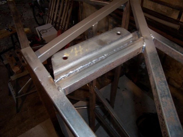
Mark Allanson
|
| posted on 8/1/03 at 07:57 AM |
|
|
Steve,
The image is of the bracket in the early stages, but even then, the bracket is welded at the top, it extends up the slanted upright about 2.5" and is
fully welded.
It now has seat belt anchorages at the bottom extending 4" upwards and these are fully welded to fill the gap and then there is another filler panel
completely closing off - I will post a shot tonight to illustrate (at work at the moment!!) Shhhh
|
|
|
jollygreengiant
|
| posted on 8/1/03 at 09:25 AM |
|
|
As Steve pointed, out the rubber bushes are and should always be thought of as "compliance " bushes and should be treated as such. When it comes to
final assembly you should always (where you have a bush) leave the suspension bolt loose until you have the vehicle fully built, loaded and on the
ground so that the suspension is fully loaded to nmormal running. THEN you should go round and tighten ALL the bolts. This approach will mean that the
bush only has to do its job, rather than try & allow all the suspension to align, thereby reducing the amount of stress that is tranfered to it and
the rest of the suspension.
Sorry if I'm trying to teach granma to suck eggs again. But some of the newbies might not be aware of the concept like the rest of you.
Enjoy.
|
|
|
Mark Allanson
|
| posted on 8/1/03 at 06:44 PM |
|
|
Steve,
As promised, the image of my reinforcements for the rear brackets (back at home now!!)
You can see the extra welds on the upper part of the bracket where it meets K2. I think the bracket would work even without M2, but I would not like
to try it. The seat belt mounts now do 2 jobs and the large filler plate (1.6mm) adds to the strength.
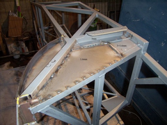 
Rescued attachment DCP_0401mm copy.jpg
|
|
|
Alan B
|
| posted on 8/1/03 at 07:12 PM |
|
|
quote:
Originally posted by Rorty
.........Allan B: I like the rigidity of your jig, but it does seem to be dependant on the accuracy of the location of two initial brackets. By the
same token, it doesn't register against the chassis........
Hi Bob,....not quite, it locates all 4 at once, but granted the lower 2 are clamped and measured from the bottom, by measuring the fixture that
is...not relying on the brackets themselves, just the holes (via the fixture).
I wasn't suggesting it was completely applicable for a "book" locost, just throwing in some more ideas. particularly the lower tapped bar to give
spacing and the 2 allen bolts to align the brackets, with the nuts to clamp the brackets.
I do agree with completely though about the shortcomings of the book...I use it only for occasional inspriation...never anything technical
|
|
|
darren(SA)
|
| posted on 8/1/03 at 07:27 PM |
|
|

When welding my brackets on, I just threaded a 14mm rod through with spacers to ensure alignment which worked pretty well.I did the same with the
bottom only with bushes.getting them parallel to each other(looking from the side,I simply measured the distance between the rods on either side until
100%(I hope).looking from the top, well I took a chance, the segment that the brackets/bushes are welded onto/into is a perfect plane(my perfect not
an engineers perfect ). I'm sure all the engineers reading this are grinding their teeth at the moment but it seems to be OK,well we'll see on my
1st corner. ). I'm sure all the engineers reading this are grinding their teeth at the moment but it seems to be OK,well we'll see on my
1st corner.
Well enough of my waffling, my next concern is the bushes! I wasn't too concerned until reading the above posts: I wasn't too concerned until reading the above posts:
We've got a company that specializes in rubber to metal bonding,rubber moulding and polyurethane moulding(you'd think I'd know whats going on) so I
would be able to make any bush nescessary.
First of all, all our bushes are made out of 90 shore rubber with an inner steel bush which was designed to rotate around the threaded rod.Now from
what I've picked up from you guys is that we must replace these with polyurethane bushes?
Do you think the Ideal thing to do would be to bond the urethane to the outer bush on the suspension arm with the loose inner bush? What shore
hardness should I use?
One thing i did not agree with the book is the suspension bolt diameter.If I'm not mistaken, I think the book says m8? We went m14 just to be safe and
will go m16 on the next one to be safer.Anybody else find this?
Ok my hands are sore and I'm sure you guys are yawning by now
thanks
darren
PS ignore the file at the bottom of the post. Please feel free to criticise my suspension as it is my 1st build and am always willing to learn!
[Edited on 8/1/03 by darren(SA)]
Rescued attachment lotus26.JPG
|
|
|
interestedparty
|
| posted on 8/1/03 at 08:44 PM |
|
|
If you want to use polyurethane bushes, then they need to be resilient enough to provide the full required suuspension movement by the material itself
twisting. Given the choice I would go for the type which is designed to rotate around the inner steel tube (which needs to be clamped into position by
the brackets being squeezed closed by the suspension bolts). Most hard plastics can be used for this purpose, Jon Ison has used a type of nylon with
selflubrucatin properties, easily machined in a lathe. The important thing is that the inner tube be very slightly longer .2-.5mm than the assembled
bush. This is the type to go for, forget the polyurethane and the rubber, you don't need the hassle, and the type I have described have been proven
to work extremely well
John
As some day it may happen that a victim must be found,
I've got a little list-- I've got a little list
Of society offenders who might well be underground,
And who never would be missed-- who never would be missed!
|
|
|
stephen_gusterson
|
| posted on 8/1/03 at 11:11 PM |
|
|
quote:
Originally posted by Mark Allanson
Steve,
As promised, the image of my reinforcements for the rear brackets (back at home now!!)
Yep. That would meet my idea of a bit of redundancy - nice idea!
Thanks also Rorty for clearing up my slight misunderstanding of rubber bushes. (I havnt used em!) Must say all the cars I have worked on have had
pretty 'springy' action on their bushes.
atb
Steve
|
|
|
stephen_gusterson
|
| posted on 8/1/03 at 11:18 PM |
|
|
quote:
Originally posted by interestedparty
If you want to use polyurethane bushes, then they need to be resilient enough to provide the full required suuspension movement by the material itself
twisting. Given the choice I would go for the type which is designed to rotate around the inner steel tube (which needs to be clamped into position by
the brackets being squeezed closed by the suspension bolts). Most hard plastics can be used for this purpose, Jon Ison has used a type of nylon with
selflubrucatin properties, easily machined in a lathe. The important thing is that the inner tube be very slightly longer .2-.5mm than the assembled
bush. This is the type to go for, forget the polyurethane and the rubber, you don't need the hassle, and the type I have described have been proven
to work extremely well
John
One of the bush companies (polyflex???) have a website that says you can buy rod to machine your own bushes from.
The rod does not come with any centre hole or metal liner.
atb
steve
[Edited on 8/1/03 by stephen_gusterson]
|
|
|
Rorty
|
| posted on 9/1/03 at 01:37 AM |
|
|
We seem to be back onto the topic of bushes, which myself and others ranted about on another thread.
DarrenSA:
quote:
One thing i did not agree with the book is the suspension bolt diameter.If I'm not mistaken, I think the book says m8? We went m14 just to be safe
and will go m16 on the next one to be safer.
8mm is fine, only if you're using metric 10.9 grade bolts (nothing to do with imperial grade 10). I would prefer 3/8" or 10mm just to add a safety
margin. No need for anything larger, unless you're using mild steel "garden" bolts, in which case you shouldn't be building a car.
Interestedparty:
quote:
If you want to use polyurethane bushes, then they need to be resilient enough to provide the full required suuspension movement by the material itself
twisting. Given the choice I would go for the type which is designed to rotate around the inner steel tube (which needs to be clamped into position by
the brackets being squeezed closed by the suspension bolts). Most hard plastics can be used for this purpose, Jon Ison has used a type of nylon with
selflubrucatin properties, easily machined in a lathe. The important thing is that the inner tube be very slightly longer .2-.5mm than the assembled
bush. This is the type to go for, forget the polyurethane and the rubber, you don't need the hassle, and the type I have described have been proven
to work extremely well
This was addressed in another thread, but now is getting a bit cloudy.
PU bushes are designed to rotate. Period. All PU bushes require a crush tube that is the exact length of the inside of the bracket it is being
mounted in. The softer grades (Shore 60 and Shore 70) when assembled, must be between 0.5mm and 1.0mm longer than the inner crush tube. In other
words, the crush tube is SHORTER than the (assembled length) bushes NOT longer, as Interestedparty states.
The reason for this is, the softer grades of PU will distort too much if made to the precise length of the crush tube, and will let the wishbones
wobble around. By making the PU bushes LONGER, they are preloaded, which resists compaction. They can be a real sod to install because they appear to
be too big for the gap!
When using the harder grades of PU, for bushes, they should be the same length as the crush tube. Before you go cutting or sanding the faces off the
PU bushes, find out from the supplier which grade they are. Even if they seem impossibe to squeeze into the brackets, they may well be the correct
size.
Nylon itself is not the best choice for bushes, as it is not classed as self lubricating. The modified Nylons such as Poltamides (PA) is a lot better,
and has good stiffness, lubricity, and good resistance to wear and fatigue.
The top of the pile though (for suspension bushes), is Polyacetal, or just Acetal (POM) and especially any of the variations that are combined with
Teflon fibres. The POM family machine freely too, unlike PU.
There are slippier plastics such as PETP, but they aren't as suitable for this application.
The main drawback for the average DIYer building a Locost, is that the harder bush materials are very rigid, and as Syd Bridge points out, don't lend
themselves to moving anywhere other than their designed axis.
So, unless you have attached your front suspension brackets with a jig, thereby ensuring the concentricity of the bushes on a common axis, there is no
point using either POM or Shore70/80 PU.
If there is any doubt in your mind as to the accuracy of your suspension brackets, just use the softer (more common) PU bushes, but don't use
Metalastic bushes.
This is all rather moot if the suspension design is unworthy. I reiterate one of my original queries, has anyone either modeled the book suspension,
or have any positive experience of driving a finished Locost? What, if any, modifications do the roundy-roundy boys make to their front end
set-ups?
I will glady model the book set-up, but not if everyone's happy with it as it is.

Cheers, Rorty.
"Faster than a speeding Pullet".
PLEASE DON'T U2U ME IF YOU WANT A QUICK RESPONSE. TRY EMAILING ME INSTEAD!
|
|
|
Rorty
|
| posted on 10/1/03 at 02:45 AM |
|
|
Yes, and you can put turps in your engine too. It's a bit rough, but a lot cheaper than wasting your hard earned cash on expensive oil.

Cheers, Rorty.
"Faster than a speeding Pullet".
PLEASE DON'T U2U ME IF YOU WANT A QUICK RESPONSE. TRY EMAILING ME INSTEAD!
|
|
|


